
HSE-321 · Lesson 4 of 12 · 29 min
Arc flash risk assessment and labels in critical facilities
An arc flash risk assessment answers three questions about a task: is there an arc flash hazard, how likely is it that an arc flash will occur during this task and, if it does, how severe will it be? HSE-224 Lessons 4 and 5 explain the physics of arc flash and the general method of the risk assessment, including the two ways of selecting PPE, the incident energy analysis method and the arc flash PPE category method, and the information an arc flash label must contain. This lesson assumes you know that material. It focuses on what is different about arc flash risk assessment in data centers: systems that can operate in several configurations, each with a different hazard; protective schemes designed to reduce incident energy during maintenance; very high incident energies at main switchgear; and the frequent tasks, such as racking breakers and testing, that bring workers into the arc flash boundary.
The arc flash study in a critical facility
The incident energy figures on arc flash labels come from an arc flash study, an engineering analysis that models the power system, calculates the fault current available at each piece of equipment, determines how long the protective devices will take to clear an arcing fault and then calculates the incident energy at a specified working distance. In North America, most studies use the method in IEEE 1584-2018, Guide for Performing Arc-Flash Hazard Calculations, and its later amendments. DCE-310 Lesson 7 explains the engineering. What matters for the people using the results is that the study is only as good as the data and assumptions behind it.
Data centers complicate studies in three ways. First, there are many sources: two or more utility feeds, many generators that can run in parallel, UPS inverters and, in some designs, large motor loads in cooling plants. Second, there are many operating configurations: normal operation on utility, operation on generators, tie breakers closed or open, UPS on inverter, static bypass or maintenance bypass, one side of a 2N system shut down for maintenance. Third, the system changes often, with new halls, new generators and new UPS modules added in phases over many years.
A good study for a critical facility models every credible configuration and reports the worst case at each piece of equipment, or reports results by configuration so that the label or the MOP can tell the worker which value applies. The difference can be large. Closing a tie breaker so that two transformers feed one switchboard can nearly double the available fault current. Running on generators usually reduces the fault current, which sounds safer, but it can also make protective devices slower, because they may be operating in the long-time part of their trip curve. Lower current with a much longer clearing time can produce higher incident energy than the utility case.
Why clearing time dominates
Incident energy depends on many factors: available fault current, voltage, the gap between conductors, the size of the enclosure, the electrode configuration and the distance from the arc. But for a given piece of equipment, the factor that can change most is the arcing time, the time it takes for the protective device to clear the arcing fault. Incident energy is roughly proportional to arcing time. Halve the time and you roughly halve the energy. A fault cleared in 0.05 s, three cycles at 60 Hz, releases about a tenth of the energy of the same fault cleared in 0.5 s.
This is why main low-voltage switchgear in data centers can have such high incident energies. A fault on the main bus is cleared by the main breaker or by the transformer's primary protection. To coordinate with the many feeder breakers downstream, so that a fault on one feeder does not trip the whole switchboard, the main device is usually set with an intentional delay, often several tenths of a second. That delay protects uptime, but it lets an arcing fault on the main bus burn much longer than a fault on a feeder.
Reducing incident energy during maintenance
Because clearing time drives incident energy, the most effective engineering controls for arc flash in critical facilities make protective devices faster when people are working nearby. Several approaches are common.
- Energy-reducing maintenance switching. A switch, often with a blue indicating light, that temporarily sets a circuit breaker's trip unit to an instantaneous or near-instantaneous setting while work is under way. Electrical codes in both countries require energy-reducing means for large circuit breakers, typically those rated 1,200 A or more, and energy-reducing maintenance switching is one of the accepted methods.
- Zone-selective interlocking. Breakers communicate so that the breaker closest to a fault trips instantly, while upstream breakers delay only when a downstream breaker reports that it sees the fault.
- Bus differential protection. Relays compare current entering and leaving a bus and trip instantly for a fault inside the zone.
- Arc flash detection relays. Sensors detect the light of an arc, usually combined with a current check, and trip an upstream device within a few milliseconds.
- Remote racking and remote operation. Devices that let a worker rack breakers or operate switches from outside the arc flash boundary, removing the person rather than reducing the energy.
These controls only work if they are used. A maintenance switch that nobody turns on reduces nothing, and a switch left on after work can cause nuisance tripping that the operations team then disables. The MOP must say when energy-reducing maintenance switching is engaged and when it is returned to normal, and the arc flash label or a supplementary label must show the incident energy in both settings, so that the worker knows which PPE applies.
# Teaching approximation only, NOT a substitute for an IEEE 1584 study.
# Incident energy is roughly proportional to arcing time and falls with distance
# as (D_ref / D) ** x, where x depends on the equipment (about 1.5 to 2 for
# enclosed equipment). The reference value is an invented study result.
E_REF = 38.0      # cal/cm2 at the reference distance and time (illustrative)
T_REF = 0.50      # s, main breaker with intentional delay
D_REF = 610       # mm (24 in), a typical switchgear working distance
X = 1.6

def energy(t, d):
    return E_REF * (t / T_REF) * (D_REF / d) ** X

def boundary(t, threshold=1.2):
    # distance at which incident energy falls to 1.2 cal/cm2 (5.0 J/cm2)
    return D_REF * (E_REF * (t / T_REF) / threshold) ** (1 / X)

for label, t in [("normal settings", 0.50), ("generator mode", 0.80), ("maintenance switch on", 0.05)]:
    e = energy(t, D_REF)
    b = boundary(t)
    print(f"{label:22s} t = {t:4.2f} s  E at 610 mm = {e:5.1f} cal/cm2"
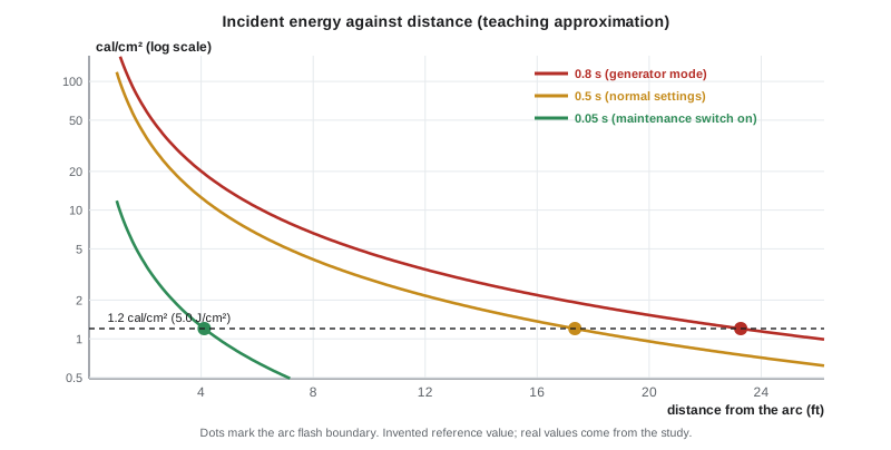
f" arc flash boundary about {b/1000:4.1f} m ({b/25.4/12:4.1f} ft)")normal settings t = 0.50 s E at 610 mm = 38.0 cal/cm2 arc flash boundary about 5.3 m (17.3 ft) generator mode t = 0.80 s E at 610 mm = 60.8 cal/cm2 arc flash boundary about 7.1 m (23.3 ft) maintenance switch on t = 0.05 s E at 610 mm = 3.8 cal/cm2 arc flash boundary about 1.3 m ( 4.1 ft)
The approximation, using an invented reference value, shows the pattern a real study would show. With normal settings the incident energy at the working distance is high enough that only the heaviest arc-rated suits would offer protection, and the arc flash boundary extends many meters. In generator mode, slower clearing makes it worse. With the maintenance switch on, the energy falls to a level that a moderate arc-rated clothing system can handle and the boundary shrinks to about a meter. In a real facility the study would calculate each value properly, but the lesson is the same: arc flash risk depends on how the system is set up at the moment of the task.
Arc flash labels in data centers
Electrical codes require arc flash warning labels on equipment such as switchboards, panelboards, industrial control panels and motor control centers that is likely to require examination, adjustment, servicing or maintenance while energized. CSA Z462 and NFPA 70E go further and set out what the label must contain: the nominal system voltage, the arc flash boundary and at least one of the following: the available incident energy and the corresponding working distance, or the arc flash PPE category, the minimum arc rating of clothing, or site-specific PPE requirements. The standards do not permit both the incident energy and the PPE category on the same label, because the two methods must not be mixed. Many sites also show the limited and restricted approach boundaries and the date of the study.
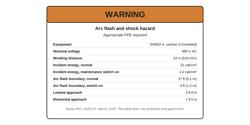
Several features of labels matter particularly in critical facilities.
Signal words. Many sites use the signal word WARNING on labels where incident energy is within the range that arc-rated PPE can protect against, and DANGER where the energy exceeds the highest-rated PPE the site provides, often 40 cal/cm² (167 J/cm²), or where shock hazards are very high. The words follow the hazard sign standards the site uses, and the meaning must be explained in training. A DANGER label at a main switchboard is not a challenge to find heavier PPE; it is a statement that energized work on that equipment must not be done.
Multiple values. Where incident energy varies significantly with the system configuration or with energy-reducing maintenance switching, sites may show more than one value, or show the worst case and give configuration-specific values in the MOP. What matters is that the worker can tell, without guessing, which value applies to the task they are about to do.
Currency. A label is only valid for the system as it was modeled. Both standards require the arc flash risk assessment to be reviewed at intervals not exceeding five years, and whenever a major modification or renovation takes place. In a growing data center, a new generator, a new transformer or a changed relay setting can change incident energies at equipment that was never touched. The site should track which labels each change affects and replace them before work relies on them.
Labels do not authorize work. An arc flash label tells you the hazard. It does not tell you that energized work is justified, it does not replace a permit and it does not tell you whether the equipment is in a condition that makes an arc flash more likely. A worker who sees 8 cal/cm² on a label and is wearing a 12 cal/cm² suit is not thereby authorized to work on the equipment energized.
Likelihood: tasks and equipment condition
The risk assessment must consider likelihood as well as severity. Both standards recognize that normal operation of equipment, such as closing a breaker with the doors closed and latched, is unlikely to cause an arc flash if the equipment is properly installed, properly maintained, used according to the manufacturer's instructions, has all doors closed and secured and all covers in place, and shows no evidence of impending failure. All of those conditions must be true. In a data center, the last two are sometimes doubtful. Equipment may be running close to its rating as racks are added, cooling fans in a UPS may have failed, a breaker may not have been exercised for years and infrared scans may show hot connections.
Tasks that commonly bring workers into the arc flash boundary in data centers include the following:
| Task | Why it raises likelihood | Typical controls |
|---|---|---|
| Racking draw-out breakers in or out | Mechanical stress on stabs; misalignment; racking onto a fault | Remote racking device; maintenance switch on; arc-rated PPE; de-energize the bus where practical |
| Opening doors or removing covers on energized equipment | Dropped hardware; exposure to live parts | Justify, permit and plan; de-energize where possible |
| Voltage testing to verify absence of voltage | Test probes near live parts; meter errors | Rated meter and probes; PPE appropriate to the equipment; absence-of-voltage testers |
| Infrared scanning with covers removed | Exposure to live parts | IR windows so covers stay closed (Lesson 11) |
| Operating switches on equipment in poor condition | Normal operation is no longer reliable | Repair first; operate remotely; PPE |
| Installing busway tap-off units energized | Plug-in contact with energized bus | De-energize the busway section, or justify, permit and use the manufacturer's procedure |
Worked problem
Racking a feeder breaker at Cedar Ridge
An electrician at Cedar Ridge must rack out a 1,600 A feeder breaker in the A-side 480 V switchboard so it can be replaced. The label shows 31 cal/cm² at 24 in (610 mm) with normal settings and 4.2 cal/cm² with the main breaker's energy-reducing maintenance switch on. The site has a remote racking device. The switchboard was serviced 14 months ago and its infrared scan last month was normal. How should the risk assessment proceed?
Show solution
- Ask first whether the whole switchboard can be de-energized under the A-side shutdown in a planned window; if it can, the racking is done with no energized exposure at all.
- If the bus must stay energized, confirm the breaker is open and the load it fed has been transferred, as the switching order requires.
- Engage the energy-reducing maintenance switch and confirm the indicating light, so that the 4.2 cal/cm² value applies.
- Use the remote racking device so that the electrician stands outside the arc flash boundary during racking; if any part of the task must be done within the boundary, select arc-rated PPE adequate for the incident energy that applies.
- Record the equipment condition evidence (recent maintenance and a normal infrared scan) in the risk assessment, and return the maintenance switch to normal at the end of the task as the MOP specifies.
Answer: Prefer de-energizing the bus. If that is not done, open the breaker, engage the maintenance switch to cut incident energy from 31 to 4.2 cal/cm², rack remotely from outside the boundary, select PPE for any remaining exposure, and restore the switch afterwards.
Common mistakes
MistakeAssuming generator operation is always safer because the fault current is lower.
InsteadCheck the study: slower clearing at lower current can produce higher incident energy on generators.
MistakeReading the arc flash label as permission to work energized if the PPE is heavy enough.
InsteadTreat the label as hazard information only; energized work still requires justification and a permit.
MistakeForgetting to engage, or to return, the energy-reducing maintenance switch.
InsteadWrite both steps into the MOP and verify the indicating light.
MistakeRelying on labels after adding a generator, transformer or new hall.
InsteadUpdate the study and replace affected labels before work relies on them.
MistakeTreating equipment as safe to operate normally when it shows signs of distress.
InsteadNormal operation is unlikely to cause an arc flash only if equipment is properly installed and maintained, closed up and shows no evidence of impending failure.
Summary and key terms
- Arc flash studies in data centers must model multiple sources and configurations and report the worst case or configuration-specific values.
- Incident energy is roughly proportional to arcing time, so protective device clearing time is the biggest lever for reducing it.
- Main switchgear often has very high incident energy because main devices are delayed to coordinate with feeders.
- Energy-reducing maintenance switching, zone-selective interlocking, differential protection, arc flash relays and remote operation reduce or avoid exposure.
- Labels show voltage, arc flash boundary and either incident energy or PPE category, must be kept current and never authorize energized work by themselves.
- Likelihood depends on the task and the equipment condition; normal operation is unlikely to cause an arc flash only when all the listed conditions are met.
- Arc flash study
- An engineering analysis of a power system that calculates incident energy and arc flash boundaries at equipment.
- Incident energy
- The heat energy reaching a surface at a given distance from an arc, in cal/cm² or J/cm².
- Arcing time
- The time an arcing fault lasts before a protective device clears it.
- Working distance
- The distance from the arc source to the worker's face and chest used in the study.
- Energy-reducing maintenance switching
- A switch that temporarily makes a circuit breaker trip faster while people work nearby.
- Zone-selective interlocking
- Communication between breakers so that the one nearest a fault trips without intentional delay.
- Arc flash relay
- A protective relay that detects the light of an arc and trips an upstream device within milliseconds.
- Operating configuration
- A particular arrangement of sources and switching devices, such as utility, generator or tie-closed operation.
Practice problems
Work each problem on paper first, then reveal the answer to check.
Name three operating configurations that can change incident energy in a data center.
Show answer
Utility versus generator operation, tie breakers closed or open, and UPS on bypass or one side shut down.
Why can generator operation produce higher incident energy despite lower fault current?
Show answer
Protective devices may clear more slowly at lower current, and incident energy is roughly proportional to arcing time.
Approximately how much does incident energy fall if arcing time drops from 0.5 s to 0.05 s?
Show answer
To about one tenth.
Why are main switchgear breakers usually set with intentional delay?
Show answer
To coordinate with feeder breakers so that a feeder fault does not trip the whole switchboard.
List three engineering controls that reduce arc flash energy.
Show answer
Energy-reducing maintenance switching, zone-selective interlocking, bus differential protection or arc flash relays.
What must an arc flash label show at a minimum?
Show answer
Nominal voltage, arc flash boundary and either incident energy with working distance, or PPE category, minimum arc rating or site-specific PPE.
Why may a label not show both incident energy and PPE category?
Show answer
Because the incident energy method and the PPE category method must not be mixed.
How often must the arc flash risk assessment be reviewed?
Show answer
At intervals not exceeding five years, and after major modifications.
What does a DANGER label above the site's highest PPE rating mean for energized work?
Show answer
Energized work on that equipment must not be done.
Name two conditions required before normal operation is considered unlikely to cause an arc flash.
Show answer
Properly installed and maintained equipment, doors closed and secured, covers in place and no evidence of impending failure.
Lesson quiz · 5 questions
Score 60% or more to complete this lesson.
Create a free account to save your progress, take quizzes and earn a certificate.