
HSE-321 · Lesson 6 of 12 · 29 min
Establishing an electrically safe work condition in redundant systems
An electrically safe work condition (ESWC) is a state in which the conductor or circuit part to be worked on has been disconnected from all energized parts, locked and tagged, tested to confirm the absence of voltage and, where necessary, temporarily grounded. Until that state is established and verified, the equipment must be treated as energized, with all the boundaries and PPE that implies. HSE-224 Lesson 7 explains the steps that CSA Z462 and NFPA 70E set out, and HSE-210 explains the lockout process. In most workplaces the hardest step is the last one, testing, because the isolation is simple. In a critical facility, the hardest step is often the first one: finding every source.
The steps, applied to a critical facility
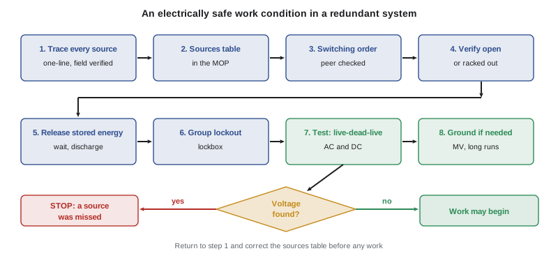
The standards describe the process in eight steps. Here they are, with the questions each raises in a data center.
- Determine all possible sources of electrical supply. Check up-to-date drawings, diagrams and identification tags. In a redundant system, this means tracing every path that can energize the equipment: normal, alternate and bypass feeds, generators, batteries, ties, paralleled modules and second cords.
- Interrupt the load current and open the disconnecting devices for each source. Opening a breaker under load is normal; opening a disconnect switch that is not rated to break load is not. The switching order (Lesson 8) sets the sequence.
- Wherever possible, visually verify that all blades of the disconnecting devices are fully open or that draw-out breakers are withdrawn to the fully disconnected position. Many data center devices are draw-out breakers that can be racked to a disconnected or withdrawn position and locked there.
- Release stored electrical energy. UPS capacitors, DC links in drives, power factor correction capacitors and long cable runs can hold charge (Lesson 7).
- Release or block stored mechanical energy. Spring-charged breaker mechanisms can close unexpectedly; discharge or block them according to the manufacturer.
- Apply lockout devices according to a documented and established procedure. In a data center this is usually a group lockout with a lockbox.
- Use an adequately rated test instrument to test each phase conductor or circuit part to test for absence of voltage. Test phase to phase and phase to ground, and verify the instrument on a known source before and after the test.
- Where the possibility of induced voltages or stored energy exists, ground the phase conductors before touching them. This is routine on medium-voltage systems and on long parallel runs.
Finding every source
The most common reason a worker is injured on equipment believed to be dead is a source that was not identified. In a critical facility the possible sources include:
| Source | Where it appears | How it can surprise you |
|---|---|---|
| Alternate utility feed or tie breaker | Main-tie-main switchboards, MV loops | Tie closes automatically or by mistake; equipment fed from the other transformer |
| Generator | ATS, paralleling gear, generator breakers | Auto-start on loss of utility while work is under way |
| UPS static bypass input | Separate bypass feed into the UPS | Remains live after the rectifier input is opened |
| UPS maintenance bypass | Wrap-around bypass cabinet | Feeds the output bus while the UPS module is isolated |
| Battery | UPS DC bus, battery cabinets | Cannot be switched off; energizes the DC bus and can back-feed the inverter |
| Paralleled UPS modules | Common output bus | Other modules energize the output of the one being serviced |
| Static transfer switch second input | STS feeding PDUs or single-corded loads | Opening one input leaves the other live |
| Second cord of dual-corded equipment | Racks, PDUs, network gear | The B cord energizes a power supply after the A cord is pulled |
| Backfeed through a transformer | PDU transformers, step-up units | Low-voltage supply energizes the high side through the transformer |
| Induced voltage or stored charge | Long parallel cable runs, capacitors | Hazardous voltage appears on isolated conductors |
Finding these sources starts with the single-line (one-line) diagram, which shows every source, switching device and connection in the power system. In a data center, the one-line is the most important safety document in the building, and it must be accurate. Facilities that grow in phases often have diagrams that lag behind the installation, so a good MOP is based on a one-line that has been field-verified for the equipment involved. That means walking the path, reading nameplates and identification tags on breakers, cables and equipment, and confirming that what is labeled A-UPS-2 output really does feed PDU A-2-3.
Many critical facilities write a sources table into the MOP for each isolation: a list of every source that can energize the equipment, the device that isolates it, the position it must be in, the lock that holds it there and the point at which absence of voltage is tested. Writing the table forces the planner to think through every path, and checking it on the night forces the crew to confirm each isolation before anyone touches anything.
Tracing sources with a model of the one-line
Large operators increasingly keep their one-line diagrams in electrical modeling software, which can trace every path from a source to a piece of equipment. The program below shows the idea with a tiny invented model of part of the Cedar Ridge A side. Each connection is listed with the device that opens it, and the search finds every source that can reach the target, together with the devices that must be opened and locked.
from collections import deque

# Tiny illustrative model of part of a UPS system. Each edge: (upstream, downstream, device)
edges = [
    ("UTILITY-A", "SWBD-A", "MAIN-A"),
    ("GEN-A", "SWBD-A", "GEN-BKR-A"),
    ("SWBD-B", "SWBD-A", "TIE-AB"),            # tie to the other side (normally open)
    ("UTILITY-B", "SWBD-B", "MAIN-B"),
    ("SWBD-A", "UPS-A-RECT", "RIB-A"),         # rectifier input breaker
    ("SWBD-A", "UPS-A-BYP", "SBB-A"),          # static bypass input breaker
    ("SWBD-A", "MBP-A", "MIB-A"),              # maintenance bypass input
    ("BATT-A", "UPS-A-DC", "BATT-BKR-A"),
    ("UPS-A-RECT", "UPS-A-DC", "internal"),
    ("UPS-A-DC", "UPS-A-OUT", "internal"),
    ("UPS-A-BYP", "UPS-A-OUT", "internal"),
    ("UPS-A-OUT", "CRIT-BUS-A", "MOB-A"),      # module output breaker
    ("MBP-A", "CRIT-BUS-A", "MBB-A"),          # maintenance bypass breaker
    ("CRIT-BUS-A", "PDU-A-3", "PDU-FDR-A3"),
]
sources = {"UTILITY-A", "UTILITY-B", "GEN-A", "BATT-A"}

def paths_to(target):
    up = {}
    for a, b, dev in edges:
        up.setdefault(b, []).append((a, dev))
    found, queue = [], deque([(target, [])])
    while queue:
        node, devs = queue.popleft()
        if node in sources:
            found.append((node, devs))
            continue
        for parent, dev in up.get(node, []):
            if all(parent != p for p, _ in devs):
                queue.append((parent, devs + [(node, dev)]))
    return found

for src, devs in paths_to("UPS-A-OUT"):
    chain = [d for _, d in devs if d != "internal"]
print(f"{src:10s} reaches UPS-A-OUT through devices: {', '.join(chain) or 'none'}")BATT-A reaches UPS-A-OUT through devices: BATT-BKR-A UTILITY-A reaches UPS-A-OUT through devices: SBB-A, MAIN-A GEN-A reaches UPS-A-OUT through devices: SBB-A, GEN-BKR-A UTILITY-A reaches UPS-A-OUT through devices: RIB-A, MAIN-A GEN-A reaches UPS-A-OUT through devices: RIB-A, GEN-BKR-A UTILITY-B reaches UPS-A-OUT through devices: SBB-A, TIE-AB, MAIN-B UTILITY-B reaches UPS-A-OUT through devices: RIB-A, TIE-AB, MAIN-B
The search finds that the output of UPS A can be energized from the A utility through either the rectifier or the static bypass, from generator A through the same two paths, from the B utility through the tie breaker and from the battery. The maintenance bypass does not appear because it feeds the critical bus, not the UPS output, but it matters for the next question: if the work is on the UPS module, the maintenance bypass is what keeps the load running, and the module output breaker (MOB-A) must be opened and locked so the bypass cannot back-feed the module. Real models are much larger, and their results must still be checked in the field, but they make it much harder to miss a path.
Isolation devices in data centers
Data center electrical equipment offers several kinds of isolation point, and each has its own rules.
Draw-out circuit breakers. Most large breakers in data center switchgear can be racked from the connected position to the test position and then to the disconnected or withdrawn position. A breaker in the disconnected position, with its racking mechanism locked, provides visible or indicated separation from the bus. Racking is a task with arc flash risk (Lesson 4), and many sites rack remotely. A breaker that is merely open, but still in the connected position, is not a good isolation point for work on downstream equipment, because it can be closed by accident, by a remote command or by an automatic transfer scheme.
Fixed breakers and switches. Molded case breakers and fused switches are locked in the open position with breaker lockout devices or padlocks on the operating handle. Some panelboard breakers need specific lockout devices; the site should stock the right devices for every type of breaker in the building.
Automatic transfer schemes. An ATS, a tie breaker scheme or paralleling gear can close automatically to restore power. Before relying on an open device in such a scheme, the automatic controls must be placed in a manual or locked-out mode according to the manufacturer and the site procedure, and the device itself locked open.
Generators. A standby generator will start automatically on loss of utility or on a test signal. If a generator is a possible source for the work, it must be prevented from starting and from connecting, typically by placing the controller in the off position, opening and locking the generator breaker and following the manufacturer's procedure for disabling the start circuit. If the work is on the generator itself, the mechanical hazards of an engine that could crank also apply.
UPS internal breakers and battery breakers. A UPS has its own breakers and switches: rectifier input, bypass input, output and battery. Some are motor-operated or controlled by the UPS logic. The manufacturer's instructions say which ones provide isolation for which work, and Lesson 7 covers them.
Group lockout in a maintenance window
A large maintenance window may involve dozens of isolation points and several crews from different employers. HSE-210 Lesson 8 explains group lockout: the isolation is performed and locked by an authorized person with operations locks, the keys are placed in a lockbox and every worker applies a personal lock to the lockbox before starting work, removing it only when their part is finished. The operations locks cannot be removed until every personal lock is off.
In a data center, the lockout coordinator usually also controls the energy isolation record or sources table, signs off each isolation as the switching order is executed and is the person who confirms, with the electrician, that absence of voltage has been verified at each work point. At shift changes, the coordinator transfers control formally so that nobody removes or adds a lock without the record being updated.
Testing for absence of voltage
Testing is the step that catches the source you missed. The standards require the test to be done by a qualified person with an adequately rated instrument, testing each phase conductor or circuit part phase to phase and phase to ground, and verifying that the instrument works on a known voltage source before and after the test. That sequence, often called live-dead-live, guards against a failed meter giving a false reading of zero.
In data centers, the test must also account for DC. A UPS battery bus, a DC power shelf or a 380 V DC distribution system needs a meter rated for DC at that voltage and a test that covers positive to negative and each pole to ground. Testing only for AC on equipment that might have a DC source is a common gap.
Both standards allow permanently mounted absence-of-voltage testers (AVTs) to be used in place of a portable meter, provided they are listed and installed according to the manufacturer, and they perform the before-and-after verification of their own operation automatically. AVTs are listed to UL 1436, which covers them, and they are increasingly installed on data center switchgear, UPS cabinets and PDUs because they let the absence of voltage be confirmed before the door is opened, removing a step that brings the worker close to exposed parts. An AVT tests only the point where it is connected, so the sources table must show that the AVT location covers the parts being worked on.
Worked problem
Isolating a PDU for transformer replacement
PDU A-2-3 at Cedar Ridge feeds 24 racks in Hall 1 through its internal transformer and panelboards. Every rack is dual-corded with its other cord on PDU B-2-3. The PDU is fed from the A-side critical bus through breaker PDU-FDR-A23 in the A-side distribution switchboard. A technician has noticed that a few racks are plugged into a convenience power strip that is fed from the PDU's panelboard and also from a B-side circuit through a small automatic transfer switch. Plan the source identification.
Show solution
- Primary source: the A-side critical bus through PDU-FDR-A23, which must be opened, racked to disconnected if it is a draw-out breaker, and locked.
- Load side: the racks' B-side cords keep the servers running, but they do not energize PDU A-2-3, because rack power supplies do not back-feed. The planner should confirm this with the equipment data rather than assume it.
- Unusual source: the small transfer switch connects a B-side circuit to the convenience strip, which is wired back to the PDU panelboard. That is a possible backfeed path into the PDU and must be isolated at its B-side breaker and locked.
- Transformer backfeed: with the panelboard energized from the B side, the PDU transformer could energize its primary at 600 V or 480 V from the secondary. This makes the unusual source dangerous, not merely inconvenient.
- Testing: test for absence of voltage on the transformer primary and secondary and on the panelboard bus, phase to phase and phase to ground, with live-dead-live verification.
Answer: Isolate both the normal feeder breaker and the B-side breaker feeding the improvised transfer switch, record both in the sources table, and test primary, secondary and panelboard. The improvised connection should then be removed and the one-line updated, because it created a backfeed path that the drawings did not show.
When the test finds voltage
If absence-of-voltage testing finds voltage, the work stops. The equipment is energized, the isolation has failed and the sources table is wrong. The crew should back away, restore the boundaries and PPE and report to the lockout coordinator and switching authority. The investigation goes back to the drawings and the field to find the missed source, and the MOP is revised before work resumes. This is not a delay; it is the ESWC process working exactly as it was designed to.
Common mistakes
MistakeOpening the rectifier input breaker of a UPS and treating the UPS as isolated.
InsteadIsolate every source: rectifier input, bypass input, maintenance bypass back-feed, battery and paralleled modules.
MistakeUsing an open but still connected draw-out breaker as the isolation point.
InsteadRack it to the disconnected or withdrawn position and lock it there, and disable any automatic closing scheme.
MistakeTesting only for AC on equipment with DC sources.
InsteadUse a meter rated for DC and test positive to negative and each pole to ground.
MistakeRelying on a one-line diagram that has not been checked against the installation.
InsteadField-verify the one-line for the equipment involved and update it when differences are found.
MistakeContinuing work after a test shows voltage because the source is probably a stray reading.
InsteadStop, report and find the missed source before work resumes.
Summary and key terms
- An electrically safe work condition requires disconnection from all sources, lockout, testing for absence of voltage and grounding where needed.
- In redundant systems, the hardest step is identifying every source, including ties, generators, bypasses, batteries, paralleled modules, second cords and backfeed.
- Accurate, field-verified one-line diagrams and a sources table in the MOP are the foundation of every isolation.
- Draw-out breakers should be racked to disconnected and locked, automatic schemes placed in a locked-out mode and generators prevented from starting.
- Group lockout, controlled by a lockout coordinator, holds the isolation for all crews.
- Testing with live-dead-live verification, including DC where applicable, catches missed sources; permanently mounted AVTs listed to UL 1436 can perform this test before doors are opened.
- Electrically safe work condition
- A state in which the parts to be worked on have been disconnected from all sources, locked out, tested for absence of voltage and grounded if necessary.
- One-line diagram
- A simplified diagram showing the sources, switching devices and connections of a power system.
- Sources table
- A list in the MOP of every source that can energize the equipment, with its isolation device, lock and test point.
- Draw-out breaker
- A circuit breaker that can be racked between connected, test and disconnected positions.
- Backfeed
- Energy flowing into equipment from an unexpected direction, such as through a transformer from its secondary.
- Live-dead-live test
- Verifying a meter on a known source, testing the circuit and then verifying the meter again.
- Absence-of-voltage tester
- A permanently mounted device that verifies the absence of voltage and checks its own operation.
- Group lockout
- A lockout method in which isolation locks are held in a lockbox to which every worker applies a personal lock.
Practice problems
Work each problem on paper first, then reveal the answer to check.
Why is identifying sources often the hardest ESWC step in a data center?
Show answer
Redundant systems have many paths: ties, generators, bypasses, batteries, paralleled modules and second cords.
List five sources that can energize a UPS output bus.
Show answer
Rectifier path from utility or generator, static bypass input, maintenance bypass back-feed, battery and paralleled modules; also a tie from the other side.
Why is an open but connected draw-out breaker a poor isolation point?
Show answer
It can be closed by accident, remotely or by an automatic scheme.
What should be done with an automatic transfer scheme before relying on an open device in it?
Show answer
Place the automatic controls in a manual or locked-out mode and lock the device open.
What does a sources table contain?
Show answer
Each source, its isolation device, the required position, the lock and the test point.
Describe the live-dead-live test.
Show answer
Verify the meter on a known source, test the circuit, then verify the meter again.
What extra testing is needed where DC sources exist?
Show answer
A DC-rated meter, testing positive to negative and each pole to ground.
What standard are absence-of-voltage testers listed to?
Show answer
UL 1436.
How can a PDU transformer create a hazard after its primary feeder is opened?
Show answer
If the secondary is energized from another source, the transformer can back-feed its primary at full voltage.
What should happen if the absence-of-voltage test finds voltage?
Show answer
Stop work, restore boundaries, report and find the missed source before resuming.
Lesson quiz · 5 questions
Score 60% or more to complete this lesson.
Create a free account to save your progress, take quizzes and earn a certificate.