
HSE-313 · Lesson 8 of 12 · 27 min
Dust collection, ventilation and isolation
Dust collection systems are essential for controlling combustible dust, and they are also among the most frequent places where dust explosions begin. A well-designed system captures dust at each source, carries it through ducts at a speed high enough to keep it moving, separates it from the air in a collector, and discharges clean air. The same system holds an explosible cloud inside the collector during normal operation and links many pieces of equipment together with ducts that can carry flame. This lesson explains how dust collection systems work, how they are designed to avoid becoming a hazard, and how isolation devices stop an explosion from traveling through them.
Local exhaust ventilation for health hazards, such as silica and welding fume, follows the same basic principles. HSE-242 covers silica control, and HSE-240 covers respirators used when engineering controls are not enough. This lesson focuses on combustible dust.
Parts of a dust collection system
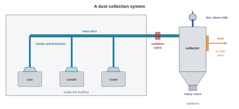
A typical system has five parts. Hoods or enclosures capture dust at the point where it is generated. Branch ducts carry dust-laden air from each hood to a main duct. The main duct carries the combined flow to the collector. The collector separates dust from air, using cyclones, fabric filter bags, cartridges or a wet scrubber. The fan provides the airflow and is usually placed on the clean-air side of the collector so that dusty air does not pass through the fan. Clean air is discharged to the outdoors or, in some cases and under strict conditions, returned to the building.
Capture and transport
Two air speeds matter. Capture velocity is the speed of air at the source needed to pull dust into the hood. It depends on how the dust is released and on cross-drafts. Transport velocity is the speed of air in the ducts needed to keep dust suspended so it does not settle. If the duct velocity falls too low, dust drops out and builds up inside the duct. That accumulation can block the duct, reduce capture at the hoods and provide fuel for an explosion that propagates through the ductwork. Typical design transport velocities for many dusts are in the range of about 3,500 to 4,500 feet per minute (about 18 to 23 meters per second). These figures are illustrative; the correct value for a particular dust should come from the system designer and recognized ventilation references.
The basic relationship between airflow, duct area and velocity is simple:
Q = A × v, where Q is airflow in cubic feet per minute (cfm), A is the duct cross-sectional area in square feet and v is the air velocity in feet per minute (fpm).
Worked problem
Airflow needed in a branch duct
A branch duct from a sander has an internal diameter of 6 inches. The designer wants a transport velocity of 4,000 fpm. What airflow is needed?
Show solution
- Diameter = 6 ÷ 12 = 0.5 ft.
- Area A = π × d² ÷ 4 = π × 0.5² ÷ 4 ≈ 0.196 ft².
- Airflow Q = A × v = 0.196 × 4,000 ≈ 785 cfm.
Answer: About 785 cfm.
import math

def airflow(diameter, velocity):
    """Q = A * v for a round duct (consistent units)."""
    area = math.pi * diameter ** 2 / 4
    return area * velocity

# SI: diameters in m, velocity in m/s -> m3/s
for d_mm in [100, 150, 200, 300]:
    q = airflow(d_mm / 1000, 20)
    print(f"{d_mm:3d} mm duct at 20 m/s -> {q:.3f} m3/s")
print()
# US customary: diameters in ft, velocity in fpm -> cfm
for d_in in [4, 6, 8, 12]:
    q = airflow(d_in / 12, 4000)
print(f"{d_in:2d} in duct at 4,000 fpm -> {q:,.0f} cfm")100 mm duct at 20 m/s -> 0.157 m3/s 150 mm duct at 20 m/s -> 0.353 m3/s 200 mm duct at 20 m/s -> 0.628 m3/s 300 mm duct at 20 m/s -> 1.414 m3/s 4 in duct at 4,000 fpm -> 349 cfm 6 in duct at 4,000 fpm -> 785 cfm 8 in duct at 4,000 fpm -> 1,396 cfm 12 in duct at 4,000 fpm -> 3,142 cfm
Worked problem
What happens when a branch is added
A main duct with an internal diameter of 12 inches carries 3,000 cfm. A new branch is added and opened, but the fan cannot increase its total flow, so the main still carries 3,000 cfm while an existing upstream branch now carries less. If the flow in a 6 inch branch falls from 785 to 450 cfm, what is the new velocity in that branch, and is there a concern?
Show solution
- Branch area = 0.196 ft² (from the previous example).
- New velocity v = Q ÷ A = 450 ÷ 0.196 ≈ 2,300 fpm.
- 2,300 fpm is well below the 3,500 to 4,500 fpm illustrative transport range.
- Dust is likely to settle in this branch, creating a blockage and an explosion propagation path.
Answer: Velocity falls far below transport velocity. Adding branches without rebalancing the system is a classic cause of dust settling in ducts; it is a change that needs management of change and a DHA review.
Duct design and maintenance
Ducts for combustible dust should be made of metal or another conductive material, bonded across joints and grounded, so that static charge cannot build up. Plastic pipe such as PVC is generally unsuitable for this reason. Duct runs should be as short and direct as practical, with long-radius bends and branch entries at shallow angles, which help maintain velocity. Cleanout ports at intervals allow inspection and removal of any settled dust. Blast gates that close unused branches help keep velocity up in the open branches, but they must be managed so that closing them does not starve other parts of the system. Flexible hoses should be conductive and as short as possible.
Collector types
| Collector type | How it works | Combustible dust notes |
|---|---|---|
| Cyclone | Spins the air so that heavier particles drop out | Often a pre-separator; the fine fraction passes on to a filter |
| Baghouse (fabric filter) | Air passes through fabric bags that trap dust; pulses of air clean the bags | Contains a dense cloud during pulsing; needs explosion protection |
| Cartridge collector | Pleated cartridges provide large filter area in a small housing | Similar hazard to baghouses; compact housings can be weaker |
| Wet collector or scrubber | Water captures dust | Common for some metal dusts; hydrogen may be generated with reactive metals, so ventilation of the collector is critical |
Where to put the collector
The safest place for a dry dust collector handling combustible dust is outside the building, away from occupied areas and from routes people use, so that an explosion inside it does not injure people or lift dust inside the building. NFPA 660 permits indoor collectors only under specific conditions, such as small volumes, or explosion protection that discharges safely, for example through vents ducted to the outside or flameless venting, or suppression. As noted in Lesson 5, BC OHS Regulation section 5.71 sets requirements for dust collectors with a volume greater than 0.6 cubic meters (20 cubic feet). Even outdoor collectors need protection, because the explosion can still travel back through the inlet duct into the building.
Returning filtered air to the building saves heating and cooling energy, but it creates a path for dust, smoke and flame to return to occupied areas if a filter fails or the collector catches fire. Where air is recirculated, NFPA 660 and good practice call for safeguards such as high-efficiency secondary filtration, monitoring and a way to divert or shut off return air when a problem is detected.
Isolation: stopping an explosion from traveling
When an explosion occurs inside a collector, the pressure and flame can travel back through the inlet duct to the machines and hoods, igniting dust in the duct and bursting out into the room. They can also travel forward from one piece of equipment to the next. Isolation devices stop this propagation. They fall into two main groups.
| Type | Examples | How it works |
|---|---|---|
| Passive | Flap valves (backflow valves), float valves, flame front diverters | Closed by the pressure wave of the explosion itself; no detection needed |
| Active mechanical | Fast-acting slide or pinch valves | A detector senses the explosion and triggers the valve to close within milliseconds |
| Active chemical | Chemical isolation (extinguishing barrier) | A detector triggers injection of extinguishing agent into the duct to quench the flame |
| Material choke | Rotary valves, screw conveyors with a plug of material | Maintains a seal of material or close clearances that flame cannot pass |
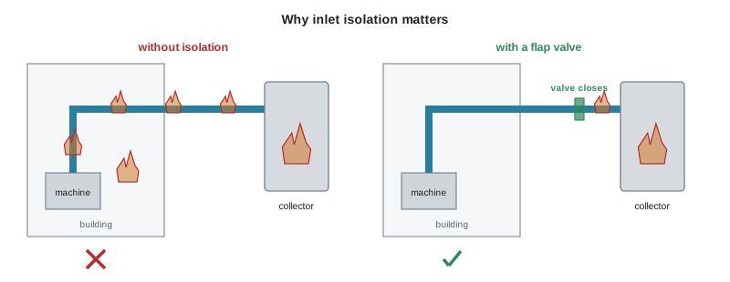
Isolation devices must be designed, located and installed according to NFPA 69 and the manufacturer's instructions, and they must be inspected and tested. Their location relative to the collector is critical: too close and the flame may already have passed, too far and the duct between may not withstand the pressure. Like explosion vents and suppression systems, isolation is a specialist design task. For this course, it is enough to know that an unprotected duct is a path for flame and that a collector with venting but no inlet isolation may still send an explosion back into the building.
Spark detection and extinguishing
Many explosions in collectors start with a spark or ember carried from a machine. Spark detection and extinguishing systems use infrared sensors in the duct to detect hot particles and trigger a water mist spray downstream to extinguish them before they reach the collector. Such systems are common in woodworking, where tramp metal in a sander or saw can create sparks. They reduce the likelihood of ignition but do not replace explosion protection.
Operating and maintaining the system
A dust collection system needs regular checks. Pressure drop across filters shows whether they are clogging; airflow or static pressure measurements at hoods and branches show whether the system is still balanced. Hoppers should be emptied regularly and never used as storage, because a full hopper can let dust back into the filter section and adds fuel. Rotary valves need maintenance to keep their seals. Isolation valves, vent panels and suppression systems need inspection and testing according to their standards. Changes to the system, such as adding branches, should go through management of change and DHA review.
Common mistakes
MistakeAdding new machines to an existing collector without checking airflow.
InsteadRebalance and verify transport velocity in every branch after any change, under management of change.
MistakeUsing plastic pipe for combustible dust ducts.
InsteadUse metal or other conductive ducts that are bonded and grounded.
MistakeUsing the collector hopper as storage.
InsteadEmpty hoppers regularly so dust does not back up into the filter section.
MistakeVenting a collector but leaving the inlet duct unprotected.
InsteadProvide isolation so an explosion cannot travel back into the building.
MistakeReturning filtered air indoors without safeguards.
InsteadUse secondary filtration, monitoring and diversion if recirculating air.
Summary and key terms
- Dust collection systems capture dust but also hold explosible clouds and connect equipment with ducts that can carry flame.
- Airflow equals duct area times velocity; ducts must keep transport velocity, illustratively about 3,500 to 4,500 fpm (18 to 23 m/s).
- Low duct velocity lets dust settle, creating blockages and propagation paths.
- Ducts should be conductive, bonded and grounded, with cleanouts and good layout.
- Dry collectors are best located outdoors; indoor collectors need specific protection, and BC regulates collectors over 0.6 m³.
- Isolation devices, passive or active, stop explosions from traveling through ducts and conveyors.
- Spark detection reduces ignition risk but does not replace explosion protection.
- Capture velocity
- The air speed at a source needed to draw dust into a hood.
- Transport velocity
- The minimum air speed in a duct that keeps dust suspended.
- Baghouse
- A collector that filters dust from air using fabric bags.
- Cyclone
- A separator that removes heavier particles by spinning the air.
- Clean-air side
- The part of the system downstream of the filter, where the air has been cleaned.
- Isolation
- Preventing an explosion from propagating through connected ducts or equipment.
- Flap valve
- A passive isolation valve closed by the explosion pressure wave.
- Chemical isolation
- Injecting extinguishing agent into a duct to stop a flame front.
- Rotary valve
- A rotating airlock that discharges material while maintaining a seal.
- Spark detection
- A system that detects hot particles in a duct and extinguishes them.
Practice problems
Work each problem on paper first, then reveal the answer to check.
Name the five main parts of a dust collection system.
Show answer
Hoods, branch ducts, main duct, collector and fan (with discharge).
What is transport velocity and why does it matter?
Show answer
The duct air speed that keeps dust suspended; below it dust settles and accumulates in ducts.
Calculate the airflow in an 8 inch duct at 4,000 fpm.
Show answer
Area ≈ 0.349 ft², so Q ≈ 1,400 cfm.
Calculate the airflow in a 200 mm duct at 20 m/s.
Show answer
Area ≈ 0.0314 m², so Q ≈ 0.63 m³/s.
Why is the fan usually on the clean-air side?
Show answer
So dusty air does not pass through the fan, which could be an ignition source and wear out.
Why are plastic ducts unsuitable?
Show answer
They are not conductive and can build up static charge.
Where is the safest location for a dry dust collector?
Show answer
Outdoors, away from occupied areas and routes.
What is the difference between passive and active isolation?
Show answer
Passive devices are closed by the explosion itself; active devices use detectors to trigger valves or agent injection.
What does a spark detection system do?
Show answer
Detects hot particles in a duct and extinguishes them with water mist before they reach the collector.
Why should hoppers not be used as storage?
Show answer
A full hopper lets dust back up into the filter section and adds fuel.
Lesson quiz · 5 questions
Score 60% or more to complete this lesson.
Create a free account to save your progress, take quizzes and earn a certificate.