
GEOM-230 · Lesson 10 of 12 · 20 min
Deflection of the vertical
The star observations of lesson 9 put the astronomic zenith at CR1 a little over 4″ away from the ellipsoid normal. Four arcseconds sounds tiny, and on a short sight it is. But every total station, level and theodolite is aligned with the local plumb line, while GNSS coordinates and every computation on the ellipsoid refer to the normal. Where the two meet, in combined networks, in trigonometric heighting on long or steep lines, in the setting out of tall structures and in the comparison of GNSS heights with leveled ones, the angle between them must be accounted for. This lesson defines the deflection of the vertical, shows how it relates to the slope of the geoid, and works out its effect on observations at the Missouri River bridge and along the pipeline.
Definition and components
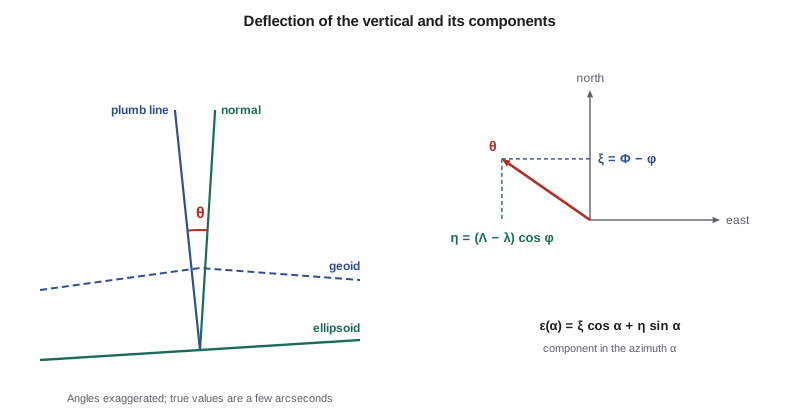
The deflection of the vertical at a point is the angle \(\theta\) between the direction of the plumb line and the ellipsoid normal through the point. It is usually resolved into two components, north–south and east–west:
With these sign conventions, a positive \(\xi\) means that the astronomic zenith lies north of the geodetic zenith, and a positive \(\eta\) that it lies east. The \(\cos\varphi\) factor converts a difference in longitude into an angle on the sphere. Strictly the deflection defined at the Earth's surface (the Helmert definition used here) differs slightly from the deflection at the geoid, because plumb lines are curved, but for engineering purposes the difference is negligible except in high mountains.
Deflections are a few arcseconds over flat terrain with uniform geology, like most of the prairies, and reach 20″ to 60″ in mountains, where the attraction of the mountain mass pulls the plumb line toward it. They also reflect hidden density contrasts: a buried dense body pulls plumb lines toward itself, while a sedimentary basin lets them lean away.
Deflections played a famous part in the history of geophysics. In the 1850s, the Great Trigonometrical Survey of India found that the difference in latitude between two stations south of the Himalaya, measured astronomically, disagreed with the geodetic difference by about 5″. John Henry Pratt calculated that the visible mass of the mountains should have deflected the plumb lines by roughly three times that amount. The deficit led Pratt and George Airy, independently, to propose that mountains are compensated by lighter material beneath them, the principle of isostasy that lesson 5 met in the negative Bouguer anomalies of the continents. The deflection of the vertical was the first measurement to reveal the structure of the crust beneath a mountain range, and it is still a sensitive probe of density contrasts at shallow depth.
Deflection and the slope of the geoid
The plumb line is perpendicular to the geoid; the normal is perpendicular to the ellipsoid. The angle between the two lines therefore equals the angle between the two surfaces, which is the slope of the geoid relative to the ellipsoid. If \(x\) points east and \(y\) north,
and in any azimuth \(\alpha\) the component of the deflection in the vertical plane of that azimuth is
A deflection of 1″ corresponds to a geoid slope of 4.85 mm per kilometer. The signs need care. A negative \(\varepsilon\) in the direction of travel means that the geoid rises in that direction relative to the ellipsoid. With \(\xi\) of about 2.4″ and \(\eta\) of about −3.4″ at CR1, the geoid falls toward the north and rises toward the east, about 11 mm per km and 16 mm per km respectively, matching the geoid grid of lesson 6.
Astrogeodetic leveling
Integrating the deflection component along a line gives the change in geoid height:
This is astrogeodetic leveling, proposed by Helmert in the nineteenth century, when astronomic stations were the only source of geoid information. It needs deflections at intervals short enough to follow their variation, a few kilometers on the plains and much closer in mountains. Today deflections come from zenith cameras or are computed from gravity data. The Vening Meinesz formula, the counterpart for deflections of Stokes's formula for geoid heights, integrates gravity anomalies to give \(\xi\) and \(\eta\), and grids such as DEFLEC2022 in the United States provide them for users. Profiles of observed deflections remain one of the best independent checks of a geoid model, because they sample its short-wavelength shape.
Effects on observations
A leveled theodolite or total station measures zenith angles from the astronomic zenith and horizontal directions in the astronomic horizon. To reduce them to the ellipsoid, the following corrections apply:
The zenith-angle correction equals the deflection component in the azimuth of the line. Ignoring it in trigonometric heighting introduces a height error of \(s\,\varepsilon\), where \(s\) is the horizontal distance: 4.85 mm per kilometer per arcsecond. Over a 561 m line with \(\varepsilon\) of about 3″ the error is close to 9 mm, enough to matter for the bridge's vertical control, though it largely cancels in reciprocal observations if the deflection is uniform. It does not cancel in one-way heighting to a monitoring target.
The horizontal direction correction is proportional to the cotangent of the zenith angle, so it vanishes for horizontal sights and grows for steep ones. Sighting the top of a bridge tower at a zenith angle of 70° from a station with a 4″ deflection gives corrections of up to about 1.5″. For a total station transferring a GNSS-derived azimuth to a steep target, or for a network that combines terrestrial angles with GNSS vectors in mountainous terrain, the correction must be applied or the deflection must be estimated in the adjustment.
Worked problem
Deflection at CR1 and its effect on heighting
At CR1, \(\xi = 2.35''\) and \(\eta = -3.45''\). Find the total deflection, the direction toward which the astronomic zenith is displaced, the component in the azimuth of CR2 (\(\alpha = 84.9^\circ\)) and the error in a one-way trigonometric height difference over the 560.1 m line if the deflection is ignored.
Show solution
- \[\theta = \sqrt{2.35^2 + (-3.45)^2} = 4.17''\]
- \[\text{azimuth} = \operatorname{atan2}(-3.45,\ 2.35) = -55.7^\circ \to 304.3^\circ\]
- \[\varepsilon = 2.35\cos 84.9^\circ + (-3.45)\sin 84.9^\circ = 0.21 - 3.44 = -3.23''\]
- \[\delta h = s\,\varepsilon = 560.1 \times \frac{-3.23}{206\,265} = -0.0088\ \text{m}\]
Answer: The deflection is 4.17″, with the astronomic zenith displaced toward the north-west (azimuth 304.3°). In the direction of CR2 the component is −3.23″, and ignoring it would make a one-way trigonometric height difference wrong by 8.8 mm.
# Deflection of the vertical: components, effects on observations, astrogeodetic geoid profile
import math
RHO = 206264.806                       # arcseconds per radian

xi, eta = 2.35, -3.45                  # at CR1, from lesson 9 (arcsec)
theta = math.hypot(xi, eta)
az_def = math.degrees(math.atan2(eta, xi)) % 360
print("total deflection =", round(theta, 2), "arcsec toward azimuth", round(az_def, 1), "deg")

def eps(alpha):                        # component of the deflection in the vertical plane of azimuth alpha
    a = math.radians(alpha); return xi * math.cos(a) + eta * math.sin(a)
def dir_corr(alpha, z):                # correction to a horizontal direction (arcsec)
    a = math.radians(alpha); return -(xi * math.sin(a) - eta * math.cos(a)) / math.tan(math.radians(z))

print()
print("azimuth  zenith  eps = zenith-angle corr  direction corr (arcsec)")
for alpha, z in ((0, 90), (84.9, 89.95), (84.9, 70.0), (180, 60.0), (270, 45.0)):
    print(format(alpha, "7.1f"), format(z, "7.2f"), format(round(eps(alpha), 2) + 0.0, "16.2f"), format(round(dir_corr(alpha, z), 2) + 0.0, "21.2f"))

# Trigonometric height difference over 561 m if the deflection is ignored
s = 560.1
print()
print("height error over", s, "m from ignoring eps:", round(s * eps(84.9) / RHO * 1000, 1), "mm")

# Astrogeodetic geoid profile along the pipeline: dN = -eps ds, integrated by the trapezoid rule
stations = [0, 5, 10, 15, 20, 25, 30, 37.9]               # km from P1
xi_k = [2.4, 2.0, 1.1, 0.3, -0.6, -1.2, -1.5, -1.9]    # arcsec, from the deflection grid
eta_k = [-3.4, -3.6, -3.9, -4.1, -4.0, -3.7, -3.5, -3.1]
az = 51.7                                               # azimuth of the line
e_k = [x * math.cos(math.radians(az)) + y * math.sin(math.radians(az)) for x, y in zip(xi_k, eta_k)]
N = [0.0]
for i in range(1, len(stations)):
    ds = (stations[i] - stations[i - 1]) * 1000.0
    N.append(N[-1] - (e_k[i] + e_k[i - 1]) / 2 / RHO * ds)
for km, e, n in zip(stations, e_k, N):
    print("km", str(km).rjust(2), " eps =", format(e, "+.2f"), "arcsec  N - N(P1) =", format(n * 1000, "+7.1f"), "mm")
print("geoid rise from P1 to P2 =", round(N[-1], 3), "m")total deflection = 4.17 arcsec toward azimuth 304.3 deg
azimuth zenith eps = zenith-angle corr direction corr (arcsec)
0.0 90.00 2.35 0.00
84.9 89.95 -3.23 0.00
84.9 70.00 -3.23 -0.96
180.0 60.00 -2.35 1.99
270.0 45.00 3.45 2.35
height error over 560.1 m from ignoring eps: -8.8 mm
km 0 eps = -1.18 arcsec N - N(P1) = +0.0 mm
km 5 eps = -1.59 arcsec N - N(P1) = +33.5 mm
km 10 eps = -2.38 arcsec N - N(P1) = +81.6 mm
km 15 eps = -3.03 arcsec N - N(P1) = +147.2 mm
km 20 eps = -3.51 arcsec N - N(P1) = +226.5 mm
km 25 eps = -3.65 arcsec N - N(P1) = +313.2 mm
km 30 eps = -3.68 arcsec N - N(P1) = +402.0 mm
km 37.9 eps = -3.61 arcsec N - N(P1) = +541.5 mm
geoid rise from P1 to P2 = 0.542 mThe table shows the two corrections for several sight lines. For the nearly horizontal sight to CR2, the direction correction is zero to two decimals, while the zenith-angle correction is the full −3.23″. For a sight at a zenith angle of 45° to the west, the direction correction reaches 2.35″. Along the pipeline, the deflection component in the line's azimuth grows from about −1″ at P1 to about −3.6″ beyond 25 km, as the line approaches an area where the plumb line leans more strongly. Integrating it gives a geoid rise of 0.54 m from P1 to P2. A GNSS height difference between the two ends of the pipeline would therefore differ from the leveled difference by about half a meter, and anyone comparing them without a geoid model would conclude, wrongly, that one of the surveys had failed.
Where deflections matter in practice
Deflections matter most where vertical and horizontal frames meet. In tunneling, where the alignment is carried underground by gyrotheodolite and traverse over kilometers, deflection changes along the route can shift breakthrough by centimeters; tunnel surveys through mountains routinely include them. In tall-structure construction, such as bridge towers and high-rise cores, plumb lines and laser plummets follow gravity while design coordinates follow the ellipsoid or a plane; over a 200 m height a 5″ deflection displaces the plumb line by 5 mm relative to the normal. In precise leveling compared with GNSS, the geoid slope is the deflection, so a geoid model with poor short-wavelength detail shows up as systematic disagreement over a few kilometers.
In inertial navigation and airborne gravimetry, deflections disturb the accelerometers and must be modeled. In combined adjustments of terrestrial and GNSS observations, modern software can treat the deflection components at each station as known values from a grid or as unknowns to be estimated. Over the gently varying prairies, deflection effects on Coulee Geomatics's ordinary work are a few millimeters and are often within tolerance, but on the bridge's monitoring network, where millimeters matter, they are applied.
| Situation | Typical effect of a 4″ deflection |
|---|---|
| One-way trigonometric height over 500 m | About 10 mm |
| Horizontal direction at zenith angle 70° | Up to about 1.5″ |
| Plumb line over a 200 m tall structure | About 4 mm |
| Astronomic versus geodetic azimuth (Laplace term, η = 4″) | About 4.5″ at the site latitude |
| Geoid change along 10 km in the deflection direction | About 0.19 m |
Common mistakes
MistakeAssuming a leveled instrument is aligned with the ellipsoid normal.
InsteadIt is aligned with the plumb line; the two differ by the deflection.
MistakeForgetting the cos φ factor in η.
Insteadη = (Λ − λ) cos φ converts a longitude difference into an angle on the sphere.
MistakeGetting the sign of the geoid slope wrong.
InsteaddN/ds = −ε: a negative deflection component means the geoid rises in that direction.
MistakeIgnoring deflection in one-way trigonometric heighting.
InsteadThe error is s ε, about 4.85 mm per km per arcsecond; reciprocal observations reduce but do not always remove it.
MistakeApplying direction corrections to horizontal sights.
InsteadThe correction is proportional to cot z and vanishes for horizontal sights.
Summary and key terms
- The deflection of the vertical is the angle between the plumb line and the ellipsoid normal.
- Its components are ξ = Φ − φ and η = (Λ − λ) cos φ.
- The deflection equals the slope of the geoid relative to the ellipsoid: 1″ is 4.85 mm per km.
- In azimuth α the component is ε = ξ cos α + η sin α, and dN/ds = −ε.
- Integrating ε along a line gives geoid height differences (astrogeodetic leveling).
- Zenith angles need a correction ε; horizontal directions need −(ξ sin α − η cos α) cot z.
- Deflections are a few arcseconds on the plains and tens of arcseconds in mountains.
- Deflection of the vertical
- The angle between the direction of gravity and the ellipsoid normal at a point.
- Meridian component
- The north–south deflection component ξ = Φ − φ.
- Prime vertical component
- The east–west deflection component η = (Λ − λ) cos φ.
- Astrogeodetic leveling
- Determining geoid height differences by integrating deflection components along a line.
- Vening Meinesz formula
- The integral that computes deflection components from gravity anomalies.
- DEFLEC2022
- The NGS grid of deflections of the vertical associated with NAPGD2022.
Practice problems
Work each problem on paper first, then reveal the answer to check.
ξ = −1.5″ and η = 2.0″. What is θ?
Show answer
2.5″.
With those components, what is ε in azimuth 90°?
Show answer
ε = η = 2.0″.
What geoid change corresponds to ε = 2.0″ over 8 km?
Show answer
ΔN = −2.0 × 4.85 × 8 = −78 mm.
What is the height error from ignoring ε = −2.5″ over 1.2 km?
Show answer
1200 × (−2.5/206 265) = −14.5 mm.
Compute the direction correction for ξ = 3″, η = 0, α = 90°, z = 60°.
Show answer
−(3 sin 90° − 0) cot 60° = −1.73″.
Lesson quiz · 5 questions
Score 60% or more to complete this lesson.
Create a free account to save your progress, take quizzes and earn a certificate.