
GAS-330 · Lesson 8 of 12 · 23 min
Welded and large-diameter gas piping
▶ Video coming soon A video version of this lesson is on the way.
When Maureen visited Crown Linen, the commercial laundry on Joyce Avenue, on September 29 to sort out its makeup air problem, she had also looked up at the gas header that ran along the back wall above the ten big tumble dryers. It was 3 in. threaded steel, installed in the 1980s, and years of lint, steam and dripping condensate had rusted its underside into flakes. A bubble test found two threaded joints weeping. The laundry ran six days a week and could not lose its dryers, so the owner agreed to replace the header over the weekend of Saturday, October 3, and Sunday, October 4. Bayline brought in Dario Russo of Ironline Welding, a pipe welder who did much of their large-diameter work, with Grant and Ayesha as the gas crew. Priya Nair, Bayline's safety coordinator, issued the hot work permit on Friday afternoon.
This lesson covers the piping methods used on larger and higher-pressure gas systems: steel pipe grades and schedules, when welded joints are used or required, who may weld, how welds and flanges are made and inspected, hot work around gas, supports and expansion on long runs, and the identification of elevated-pressure piping.
Steel pipe for gas
Most commercial and industrial gas piping is black carbon steel pipe, to ASTM A53 or A106. The wall thickness is described by its schedule: Schedule 40, standard weight in the common sizes, is the usual wall for gas piping, and Schedule 80 is heavier. The IFGC and NFPA 54 require steel pipe to be at least Schedule 10 for some joining methods and Schedule 40 for threaded joints, as their material sections set out. The nominal pipe size, NPS, is a name, not a measurement: an 3 in. pipe has an outside diameter of about 3.5 in. and, in Schedule 40, an inside diameter of about 3.07 in..
Pipe for elevated-pressure work is bought with its mill markings and, on larger jobs, its mill test reports, which record the material's chemistry and strength. A specification may require them to be kept with the job records, so that the pipe in the wall can be traced to the steel it came from.
Threaded, press-connect, flanged and welded joints
Small gas piping is usually threaded. As pipe size and pressure rise, threaded joints become harder to make tight and more likely to leak under vibration and thermal cycling, and the codes limit them. The IFGC and NFPA 54 allow threaded, welded, flanged and listed mechanical joints, but above 5 psig inside a building, one of the conditions for higher pressure is that the joints be welded or brazed, or flanged with welded pipe-to-flange connections. Even where threads are allowed, engineers often specify welded steel for large, long and elevated-pressure mains because a welded system has far fewer potential leak points.
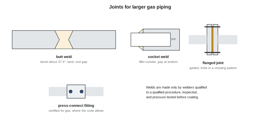
- Butt welds join pipe ends that have been beveled, typically to about 37.5 degrees with a small flat land, and set with a small root gap, so that the weld can penetrate the full wall. They are the standard joint on 2-1/2 in. and up and are used on smaller sizes too.
- Socket welds join small pipe into socket-weld fittings with a fillet weld around the outside, with a small gap left at the bottom of the socket so that the pipe can expand.
- Flanges make joints that can be taken apart, at meters, valves, strainers and equipment. Weld-neck or slip-on flanges are welded to the pipe and bolted together with a gasket rated for natural gas. Bolts are tightened in a crossing pattern, in stages, to the specified torque, so that the gasket is squeezed evenly.
- Press-connect fittings certified for gas, crimped onto pipe with a powered tool, are used in some sizes and locations where the code and the fitting's certification allow, often to avoid hot work in occupied buildings.
Who may weld
Welding gas piping is skilled work with its own qualifications, separate from the gas technician's certificate. A welding procedure specification sets out how a type of weld is to be made: the process, filler metal, pipe material and thickness range, joint design, position, preheat and so on. It is proved by welding a test coupon and testing it, recorded in a procedure qualification record. Each welder then proves that he or she can make sound welds to that procedure, in the positions to be used, by welding a performance test that is bent or examined; the result is the welder's qualification, which expires if the welder does not use it within a set period. In Ohio, project specifications and the codes' references commonly require procedures and welders qualified to ASME Section IX, and engineers often specify gas piping in buildings to ASME B31.9, Building Services Piping, or, in process plants, ASME B31.3. Dario carried his current qualification records and Ironline's procedure for carbon steel pipe.
A gas technician who is not a qualified welder does not weld gas piping, however good a welder he or she may be on a farm or in a hobby shop. The gas crew's job on a welded system is everything around the welding: laying out the piping, supporting it, making sure the pipe being cut is gas-free, fitting the valves, regulators and flanged equipment, testing, purging and putting the system into service.
Inspecting welds
Every weld is inspected visually: it should have a uniform profile, full fusion at the edges, no cracks, no undercut cutting into the pipe wall, no porosity and no excess reinforcement. Specifications for higher-pressure or critical piping may also require non-destructive examination: radiography or ultrasonic testing of a sample of welds, or of all of them, by an independent inspector. Whatever the examination, the pressure test in lesson 10 is the final proof of the whole system's tightness, and it is done before any coating, insulation or concealment that would hide the welds.
Hot work around gas
Cutting and welding produce flames, sparks and hot slag, and around gas piping that is a serious risk. The rules are the same on every job:
- Permit and fire watch. Hot work is done under a hot work permit that checks the area, removes or protects combustibles, provides extinguishers and sets a fire watch during the work and for a period after it, as the Ohio Fire Code, NFPA 51B and the owner's insurer require.
- Gas-free before cutting. Existing gas piping is never cut or welded while it contains gas. The section is isolated, depressurized, purged of gas, usually with nitrogen, and checked with a combustible gas indicator at the point of work before any torch, saw or grinder touches it. Lesson 11 covers purging out of service.
- Positive isolation. Valves can leak, so the isolation upstream is proved by watching a gauge, and on larger work a blind or a disconnected spool piece is used so that gas cannot reach the work even if a valve passes.
- No hot taps by the gas crew. Welding a branch onto a live gas pipe, a hot tap, is specialist work done by the utility or a hot-tapping contractor with special equipment and procedures. It is not part of a gas technician's work.
- Ventilation and fumes. Welding fumes and the gases from heating coated or painted pipe are hazards in themselves; the work area is ventilated and respirators are worn where the permit requires them.
At Crown Linen, Grant shut the header's inlet valve at the meter on Saturday morning, bled the header through a hose to the outdoors, and watched the gauge for fifteen minutes to prove the valve held. Then he removed a short spool of pipe downstream of the valve and capped the open end of the live side, so that the work could not be reached by gas at all. He purged the old header with nitrogen, and Ayesha checked every point Dario would cut with the combustible gas indicator: zero. Only then did Priya's permit allow the first cut.
Supports and expansion
Long runs of large pipe are heavy and move with temperature. Steel pipe expands about 0.0000065 in. per in. per °F, small numbers that become large on a long rack exposed to sun in summer and frost in winter, or on a header above hot dryers. Supports must carry the weight of the pipe at the spacings the code's support table sets for each size, be attached to structure strong enough to hold them, and allow the pipe to slide or flex where it expands. Long straight runs between fixed points may need an expansion loop or offset so that the movement bends the pipe a little instead of pushing on equipment connections.
Worked problem
How much does the header move?
Crown Linen's new header is 60 ft of 3 in. pipe between its fixed point at the meter end and its far end. It may run from 40 °F on a winter weekend to 110 °F above the dryers on a summer afternoon. How much does it grow?
Show solution
- \[60 \times 12 \times 0.0000065 \times (110 - 40) = 0.33 \text{ in.}\]
Answer: The far end moves about 1/3 in., enough to strain the dryer connections over years of cycling if the header were clamped tight at every hanger. The supports along the header were roller hangers, and each dryer's connection included its certified flexible connector, which takes up the movement.
Worked problem
What does each hanger carry?
3 in. Schedule 40 steel weighs about 7.6 lb per foot, and gas adds almost nothing. The hangers are spaced at 10 ft (a typical spacing; check the code's table). What load does each hanger carry?
Show solution
- \[7.6 \times 10 = 76 \text{ lb}\]
Answer: Each hanger and its anchor carry about 76 lb, plus any valve or regulator nearby, which can easily double the load at that hanger. Valves and regulators are supported on their own, not left hanging on the pipe.
Protection and identification
Above-ground steel gas piping is painted to protect it from corrosion, and in damp, corrosive or washdown areas, such as Crown Linen's, the coating system is chosen for the conditions, and the pipe is kept away from condensate drips and wet walls where possible. Piping that could be struck by forklifts or vehicles is protected by guards or bollards. Gas piping is identified: the IFGC and NFPA 54 require identification of gas piping where it could be confused with other piping, and many specifications and owners require labels showing gas and pressure at intervals so that nobody mistakes a gas main for compressed air or water, and nobody assumes a 5 psig line is at house pressure.
What the crew did at Crown Linen
Over Saturday, Dario cut out the old header in sections, and Grant and Ayesha carried the rusted pipe out to the bin. The new header went up on new roller hangers, bolted to the building's steel, with its underside kept clear of the condensate line that had rusted the old one. Dario butt-welded the 3 in. Schedule 40 header from a fixed point at the meter end, with weld-neck flanges at the inlet valve and at a new strainer, and socket-welded 1 in. branch outlets to each dryer and to the boiler's train. Ayesha checked each weld visually with Dario as he finished it, and logged its number on a sketch of the header, a habit Dario insisted on. "If one ever leaks," he said, "I want to know who welded it and when."
By eight on Saturday evening the header was complete. It was primed and left unpainted at the welds until after the pressure test, and the crew left it overnight with the inlet spool still out. The test and the purge on Sunday are the subject of lessons 10 and 11.
Flanged joints in practice
A flanged joint is only as good as its gasket and its bolting. The gasket must be of a material and type rated for natural gas at the system's pressure and temperature, usually a compressed non-asbestos or spiral-wound gasket for steel flanges, and it is used once: a gasket that has been compressed and released does not seal reliably a second time. The flange faces must be clean and undamaged, the gasket centered, and the bolts tightened in a crossing pattern in several passes, to the torque the specification or the gasket maker gives, so that the gasket is compressed evenly all round. Flanges at strainers, meters and equipment are where a system is opened for maintenance, so spare gaskets of the right size and rating are worth keeping on the job.
Common mistakes
MistakeLetting someone without a current qualification weld gas piping.
InsteadUse welders qualified to the procedure being used, and check their cards.
MistakeCutting into existing gas pipe that has only been shut off.
InsteadIsolate, depressurize, purge and test gas-free at the point of work first.
MistakeTrusting one closed valve as the only isolation for hot work.
InsteadProve the valve holds and use a blind or removed spool on larger work.
MistakePainting or insulating welds before the pressure test.
InsteadTest first, then coat.
MistakeClamping a long hot header tight at every hanger.
InsteadAllow for expansion with sliding supports, loops or flexible connections.
MistakeLeaving valves and regulators hanging on the pipe.
InsteadSupport heavy components separately.
Summary and key terms
- Larger and elevated-pressure gas mains are usually black carbon steel pipe, commonly Schedule 40, sized by nominal pipe size.
- As size and pressure rise, the codes limit threaded joints and, above 5 psig indoors, the IFGC's conditions include welded or brazed joints, and many specifications call for welded mains.
- Butt welds, socket welds, flanges and certified press-connect fittings each have their place.
- Welding is done only by welders qualified to a qualified procedure, commonly to ASME Section IX, with piping often specified to ASME B31.9 or B31.3; the gas crew isolates, supports, tests and purges.
- Welds are inspected visually and, where specified, by non-destructive examination, and tested before coating.
- Hot work needs a permit and fire watch, gas-free verification at the point of work and positive isolation; hot taps are specialist work.
- Supports carry the pipe at the code's spacings and allow for expansion, and piping is protected and identified.
- Schedule
- A designation of a steel pipe's wall thickness, such as Schedule 40.
- Nominal pipe size
- The name of a pipe size, NPS, which is not its actual outside or inside diameter.
- Welding procedure specification
- A written, qualified procedure that sets out how a type of weld is made.
- Welder qualification
- Proof, by a tested weld, that a welder can make sound welds to a procedure.
- Butt weld
- A full-penetration weld joining beveled pipe ends.
- Hot work permit
- A written authorization that sets the precautions for cutting, welding or other spark-producing work.
- Hot tap
- Welding a branch onto a live pipe and cutting into it under pressure, done only by specialists.
Practice problems
Work each problem on paper first, then reveal the answer to check.
Why do the codes limit threaded joints on larger pipe?
Show answer
Large threaded joints are harder to make tight and more likely to leak under vibration and temperature changes.
Who may weld gas piping?
Show answer
Only a welder qualified to a qualified procedure for that work.
What must be done before cutting into existing gas piping?
Show answer
Isolate it, depressurize it, purge it and confirm it gas-free at the point of work.
How much does 100 ft of steel pipe grow for a 90 °F rise?
Show answer
100 × 12 × 0.0000065 × 90 = 0.70 in.
Why did Dario log every weld on a sketch?
Show answer
So that any weld could later be traced to the welder and the date.
Lesson quiz · 5 questions
Score 60% or more to complete this lesson.
Create a free account to save your progress, take quizzes and earn a certificate.