
GAS-330 · Lesson 7 of 12 · 25 min
Sizing piping for elevated pressures
▶ Video coming soon A video version of this lesson is on the way.
On Thursday, October 1, Maureen set Ayesha up at the long table in Bayline's office with the Keystone Coatings drawings, a scale rule, a calculator and a printed sizing table. The utility had approved 5 psig delivery, the welding subcontractor wanted a material list by Monday, and Maureen wanted Ayesha to size the main herself, with Maureen checking. "You sized house piping in your first year," Maureen said. "This is the same method with three differences: you get to choose the pressure drop, you have to make sure every line regulator still gets enough pressure at the end, and the downstream side of each regulator is a separate little system you size all over again."
This lesson explains how elevated-pressure piping is sized: choosing the design pressure drop, using the longest-length method with elevated-pressure tables, handling fittings and future load, and sizing the low-pressure piping downstream of each line regulator. It uses SAMPLE tables made for this course; on a real job, the tables or formulas in the IFGC and NFPA 54 are used.
What sizing has to achieve
A gas pipe is the right size when, with every appliance it serves firing at full input at the same time, the pressure at each appliance or line regulator is still high enough for it to work. Three quantities decide it: the flow, from the connected load; the length of pipe the gas must travel, including allowances for fittings; and the pressure drop allowed between the start of the pipe and its far end. More flow, more length or less allowed drop all mean bigger pipe. Gas technicians normally size from the codes' tables, each calculated for one gas, one pipe material, one inlet pressure and one allowed drop.
For standard 7 in. w.c. systems, the allowed drop is small, typically 0.5 in. w.c., because the appliances need most of the delivery pressure. On elevated-pressure systems the designer has much more freedom: the main only has to deliver enough pressure to the line regulators, and line regulators can take a wide range of inlet pressures. The codes provide tables for common combinations, such as 2 psig with a 1 psi drop, or 5 psig with a 3.5 psi drop.
Choosing the design drop
The design drop is chosen by working backward from the far end. Every line regulator has a minimum inlet pressure for its rated capacity, from the maker's table, and every appliance train that takes the elevated pressure directly has a minimum inlet pressure on its plate. The pressure at the end of the main, with the system at full load, must be at least the highest of those minimums, with a margin. The allowed drop is then the delivery pressure minus that end pressure.
Worked problem
Keystone's design drop
Keystone's delivery pressure is 5 psig. The cure oven's train needs at least 2 psig at full input, and the line regulators chosen for the other appliances deliver their rated capacities with inlet pressures down to 1 psig. What drop can the main be designed for, and which table suits it?
Show solution
- The highest minimum at the far end is the oven's 2 psig, and the oven sits at the end of the main, so the end pressure must be at least 2 psig.
- Allowing a margin, design for an end pressure of about 2 psig:
- \[5 - 2 = 3 \text{ psi allowed}\]
- The SAMPLE table for 5 psig with a drop to 1.5 psig uses a 3.5 psi drop, which is more than allowed here, so the pipe chosen from it must be checked: Ayesha used it for a first pass, then checked the end pressure with the oven's branch at the larger size.
Answer: Where the code's standard tables do not match the drop a job needs, the codes' pipe-flow formulas let the designer calculate the capacity at the exact pressures. Many contractors use the codes' published software or spreadsheets built on those formulas, checked by hand on key sections.
The longest-length method
Both codes accept the longest-length method, the one most technicians learn first. The length used to read the table for every section of the system is the length from the meter to the farthest outlet, and each section is then sized for the load it carries. Using the longest length everywhere is conservative, because sections near the meter really see less pressure drop than the far end, and it is simple, which is why it is used for most systems. The codes also describe a branch length method, in which each branch is sized using the length to its own farthest outlet for the branch section and the total length for the main, giving smaller pipe in some places; it is used where the savings matter.
Fittings add resistance. Tables assume a reasonable number of fittings in the length, and for systems with many elbows and tees a designer adds an allowance, often expressed as an equivalent length of straight pipe per fitting, or as a fixed share added to the measured length. NFPA 54's annex gives equivalent lengths for common fittings. On long, straight rack runs like Keystone's, the allowance is small; in a crowded mechanical room with a dozen elbows it is not.
| Length (ft) | 1 in. | 1-1/4 in. | 1-1/2 in. | 2 in. | 2-1/2 in. |
|---|---|---|---|---|---|
| 100 | 3,750 | 7,700 | 11,530 | 22,210 | 35,410 |
| 200 | 2,580 | 5,290 | 7,930 | 15,270 | 24,330 |
| 300 | 2,070 | 4,250 | 6,370 | 12,260 | 19,540 |
| 400 | 1,770 | 3,640 | 5,450 | 10,490 | 16,720 |
| 500 | 1,570 | 3,220 | 4,830 | 9,300 | 14,820 |
Worked problem
Sizing the Keystone main by the longest-length method
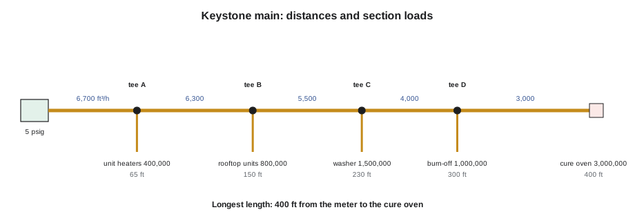
Using the SAMPLE table and a longest length of 400 ft, size each section of the main. Gas flow is 1 ft³/h per 1,000 Btu/h. Section loads: meter to A, 6,700,000 Btu/h; A to B, 6,300,000; B to C, 5,500,000; C to D, 4,000,000; D to the cure oven, 3,000,000.
Show solution
- Flows: 6,700, 6,300, 5,500, 4,000 and 3,000 ft³/h.
- Read the 400 ft row: 1-1/4 in. carries 3,640, 1-1/2 in. carries 5,450, 2 in. carries 10,490 ft³/h.
- Meter to A, 6,700: 2 in. A to B, 6,300: 2 in.
- B to C, 5,500: just over the 1-1/2 in. capacity (5,450), so 2 in.
- C to D, 4,000: 1-1/2 in. D to the oven, 3,000: 1-1/4 in.
Answer: The method gives a main that steps down from 2 in. to 1-1/4 in. along the rack. Ayesha then checked the result with the code formula, section by section. It left about 3.4 psig at the oven at full load, comfortably above the oven's minimum, because the longest-length method is conservative for every section but the last.
Judgment after the table
Sizing tables give the smallest pipe that will work today. Maureen's review of Ayesha's sizing went further. First, the section from B to C was right at the limit of 1-1/2 in., with no margin for a fitting allowance, so it went up a size. Second, Teresa had mentioned a possible second cure oven in two years, at the far end of the building. Adding 3,000,000 Btu/h to every section of the main would make the step-downs too small, and re-piping a welded rack main in a running plant is expensive. Third, every reducer in a welded main is another weld and another fitting to buy. With Teresa's agreement, they kept the whole rack main at 2 in., which carries the present load with a wide margin and the future oven with a check, and recorded the decision on the drawing. Ayesha's formula check of the final design gave about 4.1 psig at the oven at today's full load.
That judgment is the designer's, and it must be written down. A future technician who adds load to the system needs to know what the main was sized for, so Bayline's drawings carry a note stating the design delivery pressure, the design drop, the method used and any allowance for future load.
Downstream of the line regulators
Each line regulator starts a new, separate low-pressure system. Its outlet pressure, for example 12 in. w.c., is the new delivery pressure, the length is measured from the regulator to the farthest appliance it serves, and the allowed drop is chosen so that every appliance on it still gets its minimum inlet pressure. The piping is sized from the low-pressure tables for that pressure and drop. At Keystone, the rooftop units' regulator sat on the roof at the top of the riser from tee B, and the two units were 25 ft and 70 ft away; the branch to them was sized for the longer distance and their combined load, with the regulator's outlet set so that the far unit saw at least its plate minimum at full fire.
Worked problem
Checking the rooftop branch pressure
The rooftop regulator is set to 10 in. w.c. The branch piping to the two units was sized for a drop of 2 in. w.c. at full load. The rooftop units' minimum inlet pressure is 5 in. w.c. and their maximum is 14 in. w.c. Check the far unit at full load and at lockup of about 15 in 100.
Show solution
- \[10 - 2 = 8 \text{ in. w.c.} \geq 5 \text{ in. w.c.}\]
- \[10 \times 1.15 = 11.5 \text{ in. w.c.} \leq 14 \text{ in. w.c.}\]
Answer: Both limits are met. If the branch had been longer, Ayesha would have chosen a larger pipe rather than a higher regulator setting, because the setting is limited by the units' maximum inlet pressure at lockup.
Pipe materials and the tables
Each table is for one material and one wall: Schedule 40 steel, copper tubing of a given type, corrugated stainless steel tubing of a given maker, or polyethylene of a given dimension ratio. CSST and polyethylene, covered in lesson 9, have different inside diameters and, for CSST, different flow characteristics, so their own makers' tables or the code's tables for them are used, never the steel tables. Where a system mixes materials, each section is sized from the table for its material, using the same longest length and design drop.
| Step | What to decide or check |
|---|---|
| 1. Load list | Every appliance, its input and its minimum and maximum inlet pressure |
| 2. Design pressures | Delivery pressure; end pressure needed by the farthest regulator or train; allowed drop |
| 3. Lengths | Meter to farthest outlet, plus fitting allowance |
| 4. Section loads | Add the loads each section carries, nearest the meter largest |
| 5. Table or formula | Read each section at the longest length; check close calls with the formula |
| 6. Judgment | Margins, future load, fewer size changes; record decisions on the drawing |
| 7. Downstream systems | Size each line regulator's branch at its own pressure, drop and length |
| 8. Regulators | Check each line regulator's capacity at the lowest inlet pressure it will see |
Adding load to an existing elevated-pressure system
Many elevated-pressure jobs are not new systems but additions: a second oven, a new rooftop unit, a larger boiler. Before adding load, the technician checks the whole path from the meter to the new appliance, not just the new branch. The utility's meter set and service must carry the new total, which means a revised load list to the utility. The main must carry the new section loads at the design drop, read at the longest length from the existing drawing, or rechecked with the code formula. Each line regulator in the path must pass the new load at the lowest inlet pressure it will see, as Romano's Pizzeria showed in lesson 2. And any OPD sized for the old regulator must still suit the new one. This is where a design note on the original drawing, stating the design pressure, drop and any allowance for future load, saves hours: Keystone's note, written in October, already tells whoever adds the second cure oven that the main was kept at 2 in. with that oven in mind.
Common mistakes
MistakeReading the low-pressure table for an elevated-pressure main.
InsteadUse the table, or formula, for the actual inlet pressure and drop.
MistakeChoosing a design drop without checking the far end.
InsteadWork back from the highest minimum inlet pressure at the end of the main.
MistakeSizing each branch only for its own length when using the longest-length method.
InsteadUse the length to the farthest outlet for every section.
MistakeForgetting that each line regulator starts a new system.
InsteadSize its downstream piping separately at its own pressure and length.
MistakeUsing steel tables for CSST or polyethylene.
InsteadUse the table for the material actually installed.
MistakeLeaving design assumptions only in your head.
InsteadNote the design pressure, drop, method and future-load allowance on the drawing.
Summary and key terms
- Elevated-pressure piping is sized for full connected load so that every line regulator and directly fed gas train still has its minimum inlet pressure at the far end.
- The designer chooses the drop by working back from those minimums, and uses the code's tables for common combinations such as 2 psig with a 1 psi drop or 5 psig with a 3.5 psi drop, or the code's formulas for exact pressures.
- The longest-length method reads every section at the meter-to-farthest-outlet length and sizes it for the load it carries; the branch length method can give smaller pipe.
- Fittings add equivalent length.
- After the table, judgment adds margin, allows for future load and limits size changes, and the decisions are recorded on the drawing.
- Each line regulator starts a new low-pressure system, sized at its own outlet pressure, drop and length, and each material has its own tables.
- Design pressure drop
- The pressure loss allowed from the start of a piping system to its far end at full load.
- Longest-length method
- Sizing every section using the length from the meter to the farthest outlet.
- Branch length method
- Sizing branch sections using the length to their own farthest outlet, with the total length for the main.
- Connected load
- The total input of all appliances served, assumed to fire together.
- Section load
- The total load carried by one section of pipe.
- Equivalent length
- The length of straight pipe with the same resistance as a fitting or run.
Practice problems
Work each problem on paper first, then reveal the answer to check.
What three quantities decide a gas pipe's size?
Show answer
The flow, the length and the allowed pressure drop.
How is the design drop chosen on an elevated-pressure system?
Show answer
By working back from the highest minimum inlet pressure needed at the far end of the main.
In the longest-length method, which length is used for every section?
Show answer
The length from the meter to the farthest outlet.
What changes at each line regulator?
Show answer
It starts a new low-pressure system, sized at its own outlet pressure, drop and length.
Why did Keystone's main stay at 2 in. all the way?
Show answer
For margin, a possible future oven and fewer welded reducers, agreed with the owner and noted on the drawing.
Lesson quiz · 5 questions
Score 60% or more to complete this lesson.
Create a free account to save your progress, take quizzes and earn a certificate.