
GAS-230 · Lesson 6 of 12 · 29 min
Plastic venting for condensing appliances
▶ Video coming soon A video version of this lesson is on the way.
On Wednesday, November 11, Jonah spent the morning with Rosa at the new house at 14 Fairhaven Court in Hilliard, setting the two-stage condensing furnace that GAS-130 described him wiring in the afternoon. Before any wire was pulled, the furnace had to be piped for its vent and combustion air. The builder's framer had left a pair of openings in the rim joist on the east side of the house for the vent and intake, and had already run a dryer duct out through the same wall a short way along. "Plastic venting looks like plumbing," Rosa said, holding up a length of the certified pipe. "It isn't. This pipe carries flue gas under pressure, it has to drain its own condensate, and the two holes outside are a ventilation system the house's neighbors and windows have to live with. Every dimension comes out of the instruction book."
This lesson covers the plastic vent and air intake systems used with condensing, Category IV appliances: the materials, the layout, sizing by equivalent length, joining, slope and support, condensate, and terminations.
Why condensing appliances use plastic
A condensing furnace, boiler or water heater extracts so much heat from its flue gas that the gas leaves the appliance at only 95 to 140 °F, below its dew point, and condenses in the secondary heat exchanger and in the vent. The condensate is acidic, roughly as acidic as a soft drink, and it would eat through Type B or galvanized steel in a few seasons. The gas is also too cool to rise by buoyancy, so the appliance's inducer pushes it through the vent under positive pressure. A condensing vent therefore has to be gas-tight, acid-resistant and able to drain, and low flue gas temperatures make plastic the obvious material: it does not corrode, it is light, it seals with solvent-welded joints, and it is cheap.
In the US, the appliance maker's instructions decide the plastic vent material. Most condensing furnace makers list Schedule 40 PVC pipe to ASTM D1785, PVC DWV fittings to ASTM D2665, and CPVC to ASTM F441, with the primer and cement standards to match; many prohibit cellular-core pipe, and some allow it for the intake only. Many condensing boilers and water heaters, whose flue gas can be hotter, require CPVC or a polypropylene or stainless system listed to UL 1738. Plain PVC is limited to about 149 °F, which is why appliances vented in PVC have a control that limits the flue gas temperature. NFPA 54, the IFGC and the Ohio Mechanical Code all defer to the instructions for plastic vents.
Two-pipe, one-pipe and concentric layouts
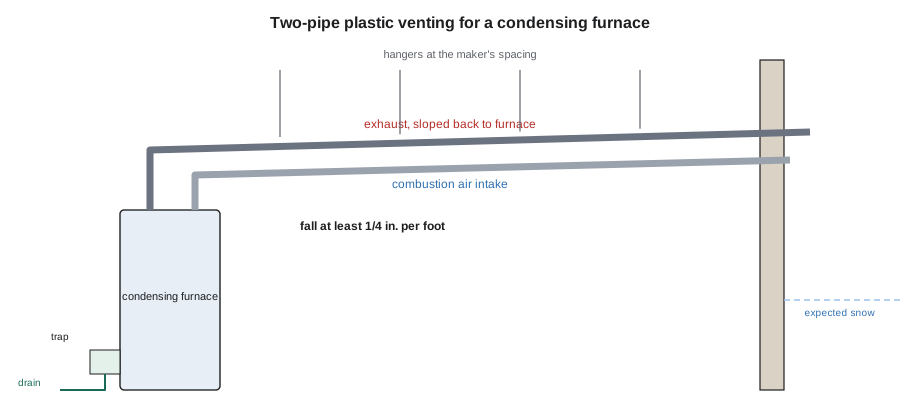
Most condensing furnaces can be installed in one of two ways. In a two-pipe or direct-vent installation, one pipe carries flue gas out and a second pipe brings combustion air in from outdoors to the furnace's sealed burner box. In a one-pipe or non-direct installation, only the exhaust pipe goes outside, and the furnace draws its combustion air from the room. Two-pipe is almost always better: the furnace uses no house air, is not affected by house depressurization, and does not pull in air laden with laundry chemicals, paint fumes or the chlorine of a pool room, which can corrode its heat exchanger. Bayline installs two-pipe whenever the instructions allow it, and always in new houses.
The two pipes can leave the house through separate terminations, an exhaust and an intake a set distance apart, or through a concentric termination kit, a single wall or roof penetration in which the exhaust runs inside a larger intake pipe. Concentric kits need only one hole and keep the two openings in a fixed relationship to each other. Either way, the kit or the layout must be one the furnace's instructions list.
Sizing by equivalent length
Condensing vents are not sized from the Category I tables. The appliance maker tests each model with its vent and publishes a table of the maximum equivalent length allowed for each pipe diameter, sometimes with a minimum length as well, and often separately for each input of a multi-model family and for each altitude. Equivalent length is the length of straight pipe plus an allowance for every fitting, because each elbow adds as much friction as a certain length of straight pipe. The instructions give the allowance for each fitting: a long-radius 90° elbow, a short-radius 90°, a 45°, and the termination kit. The exhaust and the intake are each checked against the table, and some instructions limit their combined length too.
The diameter chosen is the smallest the table allows for the equivalent length, or the next size up if the run is near the limit, but never a size the table does not list, and never a mixture of sizes the instructions do not show. Too small a pipe, too long a run or too many elbows makes the pressure switch open, as GAS-220 showed; too large a pipe on some models also causes trouble, because the burner and pressure switch were set up with a certain resistance.
| Item | Sample allowance (3 in.) |
|---|---|
| Maximum equivalent length, each pipe | 60 ft |
| 90° long-radius elbow | 5 ft |
| 45° elbow | 2.5 ft |
| Termination kit | (already included in the table) |
Worked problem
Checking the Fairhaven exhaust
Rosa's layout for the Fairhaven exhaust uses 20 ft of 3 in. pipe, four 90° long-radius elbows and two 45° elbows. Using the sample allowances, find the equivalent length and compare it with the 60 ft maximum.
Show solution
- Elbows:
- \[4 \times 5 = 20 \text{ ft} \qquad 2 \times 2.5 = 5 \text{ ft}\]
- Equivalent length:
- \[20 + 20 + 5 = 45 \text{ ft}\]
- Margin:
- \[60 - 45 = 15 \text{ ft}\]
Answer: The exhaust is well inside the sample limit. The six fittings count for more than the straight pipe; removing even one elbow from a layout often makes more difference than shortening the run.
Joining plastic vent pipe
Solvent-welded joints in plastic vent pipe are made the way the system's instructions say, and the steps are worth doing exactly every time, because a joint that fails in a vent under pressure leaks flue gas into the house. Cut the pipe square with a pipe cutter or a fine saw and a square guide. Remove the burrs inside and out, and bevel the outside edge slightly so it does not scrape the cement off as it goes in. Dry-fit the joint to check the depth and the alignment, and mark it. Clean both surfaces. Apply the primer the system calls for to the socket and the pipe end, then the cement, an even coat on the pipe and a thinner one in the socket. Push the pipe fully into the socket with a slight twist, hold it for the time the cement maker gives so it does not push back out, and wipe off the excess. Let the joints cure for the time the instructions give before the appliance is fired; the solvent vapor is flammable, so the cure is also a safety step.
Polypropylene systems are different: they are not glued but joined with gaskets and push-fit sockets, often with locking bands, exactly as their instructions say. Stainless systems use their own gaskets and clamps. Mixing a glued plastic with a gasketed one, or two brands of polypropylene, is only allowed with the adapters the instructions list.
Slope, support and expansion
Every horizontal section of a condensing vent must slope back toward the appliance, so that the condensate that forms in the pipe runs back to the appliance's trap, typically at least 1/4 in. per foot unless the instructions give a different figure. A pipe that sags or slopes the wrong way holds water, which blocks flow, trips the pressure switch, gurgles, and in cold weather can freeze. The pipe is supported at the spacing the instructions give, with hangers that let it move as it expands and that do not crush or kink it.
Worked problem
How much fall does the horizontal run need?
The horizontal part of the Fairhaven exhaust is 16 ft long. At a slope of 1/4 in. per foot, how much lower must the furnace end be than the wall end?
Show solution
- \[16 \times \tfrac{1}{4} = 4 \text{ in.}\]
Answer: The pipe must drop 4 in. from the wall back to the furnace. Rosa set a string line before hanging the pipe so the fall would be even, with no flat spots.
Plastic expands as it warms, by much more than metal, so a long straight run gets measurably longer when the furnace is running. If the pipe is fixed solidly at both ends, the expansion bends it between the supports, pulls on joints, or pushes the furnace's vent connection. Long runs are therefore laid out with an elbow or an offset that can flex, hangers that let the pipe slide, and no rigid clamping at both ends of a straight run.
Worked problem
Expansion of the horizontal run
PVC expands by about 0.00003 of its length for each degree Fahrenheit. The 16 ft horizontal run is installed at 60 °F and runs at about 120 °F with the furnace on high fire. How much longer does it get?
Show solution
- Temperature rise:
- \[120 - 60 = 60\ {}^\circ\text{F}\]
- Length in inches:
- \[16 \times 12 = 192 \text{ in.}\]
- Expansion:
- \[192 \times 60 \times 0.00003 = 0.35 \text{ in.}\]
Answer: The run grows by about 3/8 in. each time the furnace reaches high fire, and shrinks again when it stops, thousands of times a winter. The hangers and the elbow at the wall have to allow for that.
Where a vent or intake runs through an unheated space, such as an attic, a garage or a crawl space, the instructions usually require it to be insulated, or limit how far it may run there, because condensate freezes in a cold pipe and the exhaust can block with ice. GAS-220's Kowalczyk case, where an uninsulated exhaust across a cold garage caused months of lockouts, is the lesson every technician remembers.
Condensate from the appliance
The furnace's condensate drains through a trap built into or supplied with the furnace, which keeps flue gas from escaping through the drain while letting water out. The trap must be primed with water before the first firing, or flue gas can push out through it, and the condensate can back up into the collector box and trip the pressure switch. From the trap, the condensate runs by gravity to a floor drain or to a condensate pump, and many jurisdictions, maker's instructions and drain owners expect it to pass through a neutralizer, a cartridge of limestone or similar mineral that raises its pH before it reaches cast-iron drains or a septic system. Drain lines must not freeze, must not be connected directly to a drain without an air gap where the plumbing code requires one, and must be inspected at every service.
Worked problem
How much water does a condensing furnace make?
The Fairhaven furnace burns about 80 ft³ of natural gas an hour on high fire. Burning a cubic foot of natural gas produces about 0.095 lb of water vapor. If about 60 in 100 of that vapor condenses in the furnace and vent, how many US gallons of condensate does the furnace make in an hour of high fire? A gallon of water weighs about 8.34 lb.
Show solution
- Water vapor produced:
- \[80 \times 0.095 = 7.6 \text{ lb/h}\]
- Condensed:
- \[7.6 \times 0.60 = 4.56 \text{ lb/h}\]
- In gallons:
- \[\frac{4.56}{8.34} = 0.55 \text{ gal/h}\]
Answer: About half a gallon an hour on high fire, or several gallons on a cold day. That is why a blocked drain or a frozen line stops a condensing furnace so quickly.
Terminations
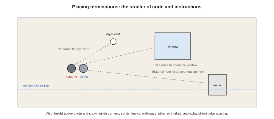
The terminations are where a condensing vent meets the outdoors, the neighbors and the house itself, and they are governed by two sets of rules at once: the appliance maker's instructions, and the code's clearances for vent terminals. Where they differ, the installer follows the stricter of the two. The rules keep flue gas away from places it could enter a building and keep the furnace's own intake from drawing in its exhaust. Typical requirements cover clearance above grade and above the expected snow line, distances from openable windows and doors, from mechanical air intakes such as an HRV or a neighbor's furnace intake, from the gas meter and its regulator vent, from inside corners, soffits and decks, and from walkways where the plume of water vapor could freeze into ice. The exhaust and intake of a two-pipe installation have their own spacing so the intake does not recirculate exhaust.
At Fairhaven, the original openings in the rim joist were too close to the dryer outlet and too low for the drifting snow that a Hilliard lot collects against an east wall. Rosa and the builder's site supervisor agreed to move the terminations: new holes higher in the rim joist, clear of the dryer duct by the distance the instructions required, the distances from the meter and its regulator vent that the instructions and Columbia Gas require, and well away from the window of the basement bedroom. GAS-120 described how the tankless water heater's terminal on this house had already been moved to the north wall for a similar reason.
Once the vent was in, Rosa checked every joint, primed the trap, let the cement cure, and fired the furnace. With her analyzer she sampled the flue gas at the test port on the furnace's vent connection and checked that the carbon monoxide was low; then she held the probe at the intake termination outside to confirm it was not drawing any exhaust back in. Her service sheet recorded the pipe class and size, the equivalent lengths of exhaust and intake, the termination positions and the results.
Common mistakes
MistakeUsing plumbing drain pipe, or mixing brands.
InsteadUse only the materials, primer and cement the appliance maker lists, or the listed system it specifies.
MistakeCounting pipe length but not elbows.
InsteadAdd every fitting's allowance to find the equivalent length.
MistakeSloping the vent toward the wall.
InsteadSlope it back to the appliance so condensate drains to the trap.
MistakeClamping a long straight run tight at both ends.
InsteadAllow the pipe to expand with sliding hangers and an offset.
MistakeFiring a new furnace with a dry trap.
InsteadPrime the trap first, or flue gas and condensate go the wrong way.
MistakePlacing the termination by the code alone or by the instructions alone.
InsteadUse the stricter of the two.
Summary and key terms
- Condensing, Category IV appliances produce cool, acidic, wet flue gas under positive pressure, so their vents must be gas-tight, acid-resistant and drained, and are usually plastic.
- In the US the maker's instructions name the plastic vent material. Two-pipe direct-vent installations take combustion air from outdoors and are preferred.
- Vents are sized from the maker's maximum equivalent length table, adding an allowance for every fitting.
- Joints are made by the system's method, with primer and cement or gaskets, and cured before firing.
- Horizontal runs slope back to the appliance, are supported as the instructions say and are allowed to expand, and runs through cold spaces are insulated.
- The trap is primed and condensate drains, often through a neutralizer.
- Terminations follow the stricter of the code and the instructions for clearances from snow, openings, intakes, meters and each other.
- Category IV vent
- A positive-pressure vent for condensing appliances that must be sealed, acid-resistant and drained.
- Two-pipe installation
- A direct-vent installation with separate exhaust and outdoor combustion air pipes.
- Concentric termination
- A single penetration with the exhaust inside a larger intake pipe.
- Equivalent length
- The length of straight pipe plus an allowance for each fitting.
- Primer
- A solvent applied before cement that softens and cleans plastic for a solvent-welded joint.
- Condensate trap
- A water seal that drains condensate while keeping flue gas out of the drain.
- Neutralizer
- A cartridge of mineral that raises the pH of condensate before it reaches a drain.
- Snow line
- The expected depth of snow at a wall, below which terminations may not be placed.
Practice problems
Work each problem on paper first, then reveal the answer to check.
Why must a condensing vent slope back to the appliance?
Show answer
So condensate drains to the appliance's trap instead of pooling in the pipe.
What does equivalent length include?
Show answer
The straight pipe plus an allowance for each elbow and fitting.
Why is two-pipe installation usually better than one-pipe?
Show answer
It uses no house air and is not affected by depressurization or indoor contaminants.
Why must the trap be primed before first firing?
Show answer
A dry trap lets flue gas out through the drain and condensate back up.
Where the code and the instructions give different clearances, which applies?
Show answer
The stricter of the two.
Lesson quiz · 5 questions
Score 60% or more to complete this lesson.
Create a free account to save your progress, take quizzes and earn a certificate.