
GAS-230 · Lesson 4 of 12 · 25 min
Sizing vents and chimney connectors
▶ Video coming soon A video version of this lesson is on the way.
On Thursday, October 1, Rosa handed Jonah a clipboard and a job she called his homework. A family in a 1970s backsplit in Westgate, on Columbus's west side had a failing mid-efficiency furnace and a ten-year-old water heater, both venting into one Type B vent that rose through a closet to the roof. They wanted to replace the furnace with another mid-efficiency model, not a condensing one, because the house had no easy route for plastic pipe and no floor drain near the furnace. "A one-for-one furnace swap still means a vent check," Rosa said. "Different furnace, different flue outlet, maybe a different input. The vent has to be right for what's connected to it on the day we leave, not what was there in 1978."
This lesson shows how Category I vents and connectors are sized. The method is the same whatever the job: gather the facts, choose the right table, read it correctly and check the limits around it. To keep the code's own tables in the code books where they belong, every table in this lesson is a sample practice table made up for learning. Its numbers are rounded and invented. On a real job, the sizing comes from the tables in NFPA 54 and the IFGC or from the vent maker's tables, together with the appliance instructions.
Why size a vent at all?
A Category I vent has to do two things at once. It has to carry all the flue gas away without letting it spill: a vent that is too small for the input has too much friction for the draft available, and the gas backs up and spills out of the draft hood or, on a fan-assisted appliance, makes the pressure switch open or forces flue gas out at joints. And it has to keep the flue gas above its dew point all the way to the top: a vent that is too large for the input carries the gas so slowly that it cools, its buoyancy falls, and its water vapor condenses on the walls. Too small spills; too large condenses and may spill at start-up. Sizing tables give the range in which a vent does both jobs.
The facts you need
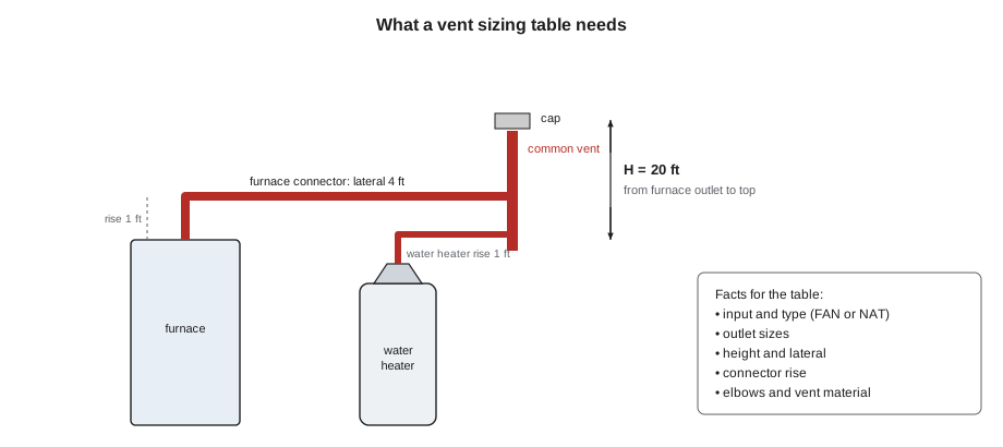
Before opening a table, gather these facts on site and write them down. Each appliance's input from its rating plate, and whether it is fan-assisted (FAN) or natural draft with a draft hood (NAT). The size of each appliance's flue outlet or draft hood outlet. The vent height, measured from the appliance's flue outlet or draft hood to the top of the vent; for a common vent, from the highest connected appliance's outlet. The lateral, the total horizontal length of the connector. The connector rise, the vertical distance from the appliance outlet to the point where the connector joins the common vent. The number of elbows. The vent material: Type B, a masonry chimney or a listed liner, and whether connectors are Type B or single-wall. And whether the vent runs through a cold space or up an outside wall, which some tables treat separately.
Reading a single-appliance table
A single-appliance table is laid out by height and lateral. For each combination it lists, under each vent diameter, three numbers: the minimum input a fan-assisted appliance must have so the vent stays warm, the maximum input a fan-assisted appliance may have, and the maximum input a natural-draft appliance may have. Natural-draft appliances have a lower maximum because their flue gas is diluted and cooler, and they usually have no minimum because the dilution air keeps the vent flow up. When the actual height or lateral falls between two rows, the conservative choice is to use the row for the lower height and the longer lateral, unless the code allows interpolation and you do it correctly.
| Vent diameter | Fan-assisted minimum | Fan-assisted maximum | Natural-draft maximum |
|---|---|---|---|
| 3 in. | 20,000 Btu/h | 60,000 Btu/h | 40,000 Btu/h |
| 4 in. | 30,000 Btu/h | 110,000 Btu/h | 70,000 Btu/h |
| 5 in. | 40,000 Btu/h | 170,000 Btu/h | 110,000 Btu/h |
| 6 in. | 55,000 Btu/h | 240,000 Btu/h | 155,000 Btu/h |
Worked problem
Sizing a vent for the new furnace on its own
Suppose the new furnace, a fan-assisted 80,000 Btu/h model, were vented alone in Type B, with a 20 ft height, a 5 ft lateral and two elbows. Using the sample single-appliance table, which diameter would work?
Show solution
- 3 in.: the fan-assisted maximum is too small:
- \[80{,}000 > 60{,}000 \text{ Btu/h}\]
- 4 in.: the input is between the minimum and maximum:
- \[30{,}000 \le 80{,}000 \le 110{,}000 \text{ Btu/h}\]
- 5 in.: also passes:
- \[40{,}000 \le 80{,}000 \le 170{,}000 \text{ Btu/h}\]
Answer: On the sample table, 4 in. is the smallest size that works and keeps the vent warmest. The connector may still not be smaller than the furnace's flue outlet.
Common venting: connectors and the common vent
When two or more appliances share a vent, it is sized in two parts. Each connector, from an appliance to the point where it joins the others, is sized from a connector table using that appliance's input and type, the total vent height and the connector's own rise. Rise matters a great deal: a connector that rises well before turning toward the vent builds up draft of its own, so a greater rise allows a greater input. Then the common vent, from the junction to the top, is sized from a common vent table using the combined input of all the appliances and their combination of types: fan-assisted plus fan-assisted, fan-assisted plus natural draft, or natural draft plus natural draft. A common vent must also be at least as large as the largest connector feeding it.
The smaller appliance is usually connected above the larger one where they enter a vertical common vent at different heights, or through a tee that suits both connectors. The codes and the vent makers have rules for how connectors join, such as using a tee rather than an elbow at the junction and keeping each connector's rise, and these are part of the sizing as much as the diameters are.
| Sample table | Use |
|---|---|
| Connector table | Size each connector by its own input, type and rise |
| Common vent table | Size the common vent by the combined input and the combination of types |
| Connector diameter | Fan-assisted maximum | Natural-draft maximum |
|---|---|---|
| 3 in. | 55,000 Btu/h | 42,000 Btu/h |
| 4 in. | 90,000 Btu/h | 60,000 Btu/h |
| 5 in. | 140,000 Btu/h | 90,000 Btu/h |
| Common vent diameter | Fan-assisted + natural draft | Natural draft + natural draft |
|---|---|---|
| 4 in. | 80,000 Btu/h | 60,000 Btu/h |
| 5 in. | 140,000 Btu/h | 100,000 Btu/h |
| 6 in. | 200,000 Btu/h | 140,000 Btu/h |
Worked problem
Sizing the Inch Park common vent
At the house, the vent height is 20 ft and each connector rises 1 ft with two elbows. The new furnace is fan-assisted, 80,000 Btu/h, with a 4 in. flue outlet. The water heater is natural draft, 40,000 Btu/h, with a 3 in. draft hood outlet. The existing common vent is 4 in. Using the sample connector and common vent tables, check each part.
Show solution
- Furnace connector, 4 in., fan-assisted maximum:
- \[80{,}000 \le 90{,}000 \text{ Btu/h} \quad \text{passes}\]
- Water heater connector, 3 in., natural-draft maximum:
- \[40{,}000 \le 42{,}000 \text{ Btu/h} \quad \text{passes}\]
- Combined input for the common vent:
- \[80{,}000 + 40{,}000 = 120{,}000 \text{ Btu/h}\]
- Existing 4 in. common vent, fan-assisted plus natural draft:
- \[120{,}000 > 80{,}000 \text{ Btu/h} \quad \text{fails}\]
- 5 in. common vent:
- \[120{,}000 \le 140{,}000 \text{ Btu/h} \quad \text{passes}\]
Answer: On the sample tables, both connectors pass but the 4 in. common vent is too small for the combined input; a 5 in. common vent would be needed. Jonah's homework answer matched what Rosa found on the real tables: the existing common vent was undersized, and had been since the old furnace's input was raised years before.
Elbows, laterals and other corrections
Sizing tables are built for a stated number of elbows, often two, and a stated lateral. Each extra elbow adds friction, so the tables come with rules for reducing the capacity when there are more turns than the table assumes, and for longer laterals. On our sample tables, use this made-up rule: reduce the maximum capacity by 10 in 100 for each 90° elbow beyond two. The real rule in the code or the vent maker's tables must be used on a job, and it may differ.
Worked problem
What extra elbows do to the furnace connector
If the furnace connector at Westgate needed four 90° elbows instead of two to get around a duct, what would the sample rule do to the 4 in. connector's fan-assisted maximum of 90,000 Btu/h? Would it still carry the 80,000 Btu/h furnace?
Show solution
- Extra elbows:
- \[4 - 2 = 2\]
- Reduction:
- \[2 \times 10 = 20 \text{ in } 100\]
- New maximum:
- \[90{,}000 \times 0.80 = 72{,}000 \text{ Btu/h}\]
- Compare:
- \[80{,}000 > 72{,}000 \quad \text{fails}\]
- A 5 in. connector instead:
- \[140{,}000 \times 0.80 = 112{,}000 \ge 80{,}000 \quad \text{passes}\]
Answer: Two extra elbows would push the furnace past the connector's capacity, so either the route is changed to remove elbows or the connector goes up a size, with an increaser fitted at the furnace outlet as the instructions allow.
NFPA 54 and the IFGC also limit how long a connector may be compared with the vent, how much it must slope, and where it may run. A connector must rise continuously toward the vent, at least 1/4 in. per foot, with no dips or sags. The horizontal length of a single-wall connector is limited to three-quarters of the vent height, and of a Type B connector to the full vent height, unless the tables allow more. A gas vent must also end at least 5 ft above the highest connected draft hood or flue collar. The connector must be supported so it keeps its slope, and it must be as short and direct as practical.
Minimum capacity and the orphan problem
The minimum column in a sizing table is what makes orphaned appliances a code matter, not just a nuisance. When a furnace is removed from a common vent and the water heater left behind, the vent that was sized for both is now carrying only the water heater's flue gas. For a natural-draft water heater the tables usually show no minimum, but they assume the vent is not wildly oversized, and an old chimney or a large B-vent can still be too big for good draft on a cold start, as Glenda's water heater showed in lesson 1. For a fan-assisted appliance left alone in a large vent, the minimum column may rule the vent out entirely. Every time an appliance is removed, replaced or added on a common vent, the remaining system has to be checked against the tables for what is now connected. That check was why Rosa made the water heater part of the Okafor-Lind quote in lesson 2.
Checking the termination
The top of the vent is part of the system too. A Type B vent ends in a listed cap, at a height above the roof that the code sets by the roof's pitch and the distance to nearby walls and roof surfaces, so that wind eddies off the roof do not push down into it. A vent that ends too low, beside a taller wall or under the eaves of a second story, may work on a calm day and spill on a windy one. The cap must be the vent maker's, undamaged and clear of nests and debris. At Inch Park the existing cap was rusted and dented and sat only a short way above the roof beside a dormer wall; Rosa included a new cap at the correct height in the quote.
Rosa's quote for the job included a new 125 mm, or 5 in., common vent from the tee to the roof, new connectors with fewer elbows, a new cap, and a draft and spillage check under worst-case conditions once the new furnace was running. The family accepted it, and the work went on the schedule for later in the fall.
Common mistakes
MistakeMatching the old vent size because it worked before.
InsteadSize the vent for the appliances that will be connected now.
MistakeReading the table for the nearest height, even if it is higher.
InsteadUse the lower height row unless you interpolate correctly.
MistakeForgetting the extra elbows.
InsteadApply the table's reduction for elbows beyond those it assumes.
MistakeUsing the natural-draft column for a fan-assisted furnace.
InsteadUse the column for the appliance's type, and check the fan-assisted minimum.
MistakeSizing only the common vent.
InsteadSize each connector by its own input and rise, and the common vent by the combined input and types.
Summary and key terms
- A Category I vent must be large enough to carry all the flue gas without spilling and small enough to keep it above its dew point.
- Sizing starts with the facts: each appliance's input and type, its outlet size, the vent height, the lateral, the connector rise, the elbows and the material.
- Single-appliance tables give, for each height, lateral and diameter, a fan-assisted minimum and maximum and a natural-draft maximum.
- Common vents are sized in two parts: each connector by its own input, type and rise, and the common vent by the combined input and the combination of types.
- Extra elbows and longer laterals reduce capacity.
- Connectors rise continuously toward the vent and are as short as practical.
- Every change to a common vent means rechecking what remains, because the minimum capacity rules out oversized vents.
- All sizing on real jobs comes from the code's or the vent maker's tables and the appliance instructions.
- Vent height
- The vertical distance from an appliance outlet, or the highest one on a common vent, to the top of the vent.
- Lateral
- The horizontal length of a vent connector.
- Connector rise
- The vertical distance from an appliance outlet to where its connector joins the common vent.
- FAN
- The table column for fan-assisted appliances.
- NAT
- The table column for natural-draft appliances with draft hoods.
- Common vent
- The part of a vent system above the junction that carries the flue gas of two or more appliances.
- Orphaned appliance
- An appliance left alone in a vent that was sized for more appliances.
Practice problems
Work each problem on paper first, then reveal the answer to check.
What happens if a Category I vent is too small?
Show answer
Too much friction for the draft; flue gas backs up and spills.
What happens if it is too large?
Show answer
The gas moves slowly, cools and condenses, and may spill at start-up.
Which input sizes a common vent?
Show answer
The combined input, using the column for the combination of appliance types.
Why does connector rise matter?
Show answer
A connector that rises before turning builds more draft, so it can carry more input.
When must a common vent be rechecked?
Show answer
Whenever an appliance on it is removed, replaced or added.
Lesson quiz · 5 questions
Score 60% or more to complete this lesson.
Create a free account to save your progress, take quizzes and earn a certificate.