
GAS-220 · Lesson 9 of 12 · 25 min
Integrated furnace control boards and fault codes
▶ Video coming soon A video version of this lesson is on the way.
On Saturday, November 7, Luis took a call from a homeowner in Gahanna who said her furnace had been humming all day even though the thermostat was off, and that now the house was cold and the furnace would not light at all. In the basement the inducer was running with no call for heat, and the status light on the control board was blinking a pattern Jonah had not seen before. Luis found the code on the chart inside the door: "internal control fault". He switched the furnace off at its disconnect, and the inducer stopped. "The board thinks it's broken, and it's probably right," he said. "But a board doesn't usually die of old age. Before I put a new one in, I want to know what killed this one, or the new one will go the same way."
Nearly every furnace built in the last twenty-five years is run by an integrated furnace control, usually called the control board or IFC: a circuit board with a microprocessor that carries out the sequence of operation, reads every safety input, drives every load, keeps track of faults and reports them through a status light. Boilers, water heaters and fireplaces have their own control modules that work the same way. This lesson explains what a control board does, how to read its terminals, settings and fault codes, how to tell a board fault from a fault the board is reporting, and how to replace a board properly.
What the board does
A control board is the furnace's decision-maker. It takes in 120 volts for the loads and 24 volts from the transformer for its own logic and the control circuit; it reads the thermostat's calls on its R, C, W, W2, Y and G terminals, as GAS-130 described; it reads the safety chain and the pressure switch; it senses the flame; and it decides, step by step, what to power next. Its outputs are relays and electronic switches that power the inducer, the igniter, the gas valve, the blower at its heating and cooling speeds, and accessories such as a humidifier or an electronic air cleaner. It times every step from its own clock: pre-purge, igniter warm-up, trial for ignition, blower-on and blower-off delays, inter-purges, retries and lockout periods.
A board also watches itself. It checks that its gas valve output is off when it should be off and that its relays have not welded shut, and it watches for a flame signal when there should be no flame. If it finds a fault in its own circuits that could be unsafe, it shuts the gas valve, often keeps the inducer running to clear the box, and flashes an internal fault code. That self-checking is part of what makes a board fail-safe, and it is what the Gahanna board was doing.
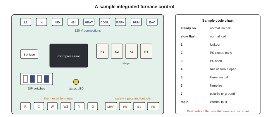
Terminals, fuse and settings
Board layouts differ from maker to maker, but the same groups appear on almost all of them. The line voltage side has terminals or plugs for the incoming hot and neutral, the inducer, the igniter, the blower's speed taps, and often a humidifier and an air cleaner output, with spare terminals called parking terminals where unused blower speed leads are kept. The low-voltage side has the thermostat terminals, the transformer secondary, the safety chain and pressure switch connections, the gas valve outputs, and the flame sense terminal. A fuse, commonly 3 or 5 amps, protects the 24-volt circuit, as GAS-130 explained; a blown fuse means a short or overload somewhere in the low-voltage wiring, and the cause is found before the fuse is replaced.
Most boards have DIP switches or jumpers that set adjustable functions: the blower-off delay in heating, the blower speeds, how a two-stage furnace decides when to go to high fire with a single-stage thermostat, and sometimes the airflow profile for an electronically commutated blower. The correct settings are in the installation instructions, chosen at start-up to suit the house and the equipment, and they are recorded on the start-up sheet. A technician changing a setting records the old and new settings on the service report.
Reading fault codes
The board reports its state through one or more status LEDs, a seven-segment display or, on communicating systems, messages on the thermostat. A steady or slowly flashing light usually means normal operation; other patterns mean a fault. A flash code is typically a number of flashes, a pause, and the same number again: three flashes, pause, three flashes. Some boards use two colors or a combination of short and long flashes. The code chart is printed on a label inside the furnace door and in the instructions. Codes are not standard between makers, and they sometimes differ between models from the same maker, so the chart on the furnace in front of the technician is the only one that counts.
A fault code tells the technician which step of the sequence failed, not which part is bad. "Pressure switch did not close" means the board did not see the switch close; it does not mean the pressure switch is faulty, as lesson 7 showed. "Flame lost after ignition" means the board stopped seeing flame; the cause could be the rod, the ground, the flame, the gas supply or the polarity, as lesson 6 showed. "Limit circuit open" means one of the switches in the chain opened; lesson 8 showed what usually makes it open. The code points to a step; the technician's tests find the cause.
| Sample code | Meaning on this sample board | Where to look next |
|---|---|---|
| Steady on | Normal, no call | Nothing |
| Slow flash | Normal, call in progress | Nothing |
| 1 flash | Lockout after failed ignition tries | Ignition sequence and flame sensing (lessons 5, 6) |
| 2 flashes | Pressure switch closed before inducer started | Switch and hose (lesson 7) |
| 3 flashes | Pressure switch did not close or opened during the cycle | Inducer, vent, hose, condensate (lesson 7) |
| 4 flashes | Limit or rollout circuit open | Airflow, rollout cause (lesson 8) |
| 5 flashes | Flame sensed with no call for heat | Gas valve leaking or stuck open; shut gas off |
| 6 flashes | Flame lost after ignition | Flame signal, ground, polarity (lesson 6) |
| 7 flashes | Reversed polarity or poor ground | Supply wiring (lesson 6) |
| Rapid flash | Internal control fault | Board and its loads |
Many boards also keep a fault history: the last several codes, often five to ten, stored in memory even after the power has been off. The instructions explain how to display it, often by pressing a button or briefly shorting two test pins, and how to clear it. The history is often the most useful information on the furnace, because many problems are intermittent and the furnace is working when the technician arrives. Bayline's practice is to read the history at the start of every call, write it on the service report, and clear it only after the repair, so the next technician starts with a clean record of what has happened since.
Worked problem
Reading a fault history
A board's history shows its last seven codes, newest first: 3, 3, 1, 3, 3, 3, 3. The board locks out after three failed ignition tries. What is the furnace most likely telling the technician?
Show solution
- Count the codes:
- \[\text{code 3: } 6 \text{ of } 7 \qquad \text{code 1: } 1 \text{ of } 7\]
- Code 3 is the pressure switch, which must close before ignition. Code 1 is a lockout, which follows repeated failed starts.
Answer: The furnace is mainly reporting pressure switch problems; the single lockout was probably the result of three failed starts in a row from the same cause, not a separate ignition fault. The technician should start with the inducer, vent, hose and condensate drainage, and should not begin by cleaning the flame rod.
Lockouts and resets
When a board has failed to light the burner after its set number of tries, usually three or four, or has lost the flame too many times in one call, it goes into lockout. Most residential boards use a soft lockout: they wait a set period, commonly one hour, and then start the sequence again on their own if the call is still there. Some faults produce a hard lockout, which stays until the power is interrupted. Turning the power off at the furnace's disconnect, or on some models turning the thermostat down and back up, resets the board. Customers learn this quickly, and a furnace that the owner has been resetting is a furnace with a fault history worth reading.
Resetting a board is not a repair. A technician may reset a board to watch the sequence and see where it fails, but never as the cure. A lockout that clears itself an hour later has left a house without heat for that hour, and it will happen again until the cause is fixed.
Is it the board?
Boards do fail: relays wear out or weld shut, circuit tracks burn, components fail from heat, moisture or a voltage surge. But boards are blamed far more often than they deserve, because the board is where the fault code appears. A board is faulty when it has every input it needs and does not produce the output the sequence calls for, or when it produces an output it should not. The test is always the same pair of measurements. First, are all the inputs for this step present: 24 volts at R and C, the call on W, the safety chain closed, the pressure switch closed? Second, is the output that should follow missing: no 120 volts at the inducer terminals, no voltage at the igniter plug, no 24 volts at the gas valve? If every input is present and the output is missing, or an output is present when it should not be, the board is faulty.
At Gahanna, the inducer had been running with no call. Luis checked the thermostat terminals: no voltage on W. With the furnace's power restored for a moment, he measured 120 volts at the inducer's board terminals with nothing calling for it, so the inducer relay's contacts were stuck closed. The board was faulty. Before ordering a new one, Luis checked the inducer motor itself: with its leads disconnected, its shaft was stiff and gritty when he turned it by hand, and when he later ran it on the new board it drew far more than its nameplate current. The inducer had been dragging for months, drawing high current through the relay contacts until they welded.
Worked problem
Why a dragging inducer welds a relay
The inducer's nameplate current is 1.1 A. With its bearings seizing, it was drawing 2.6 A. The heat produced in a relay's contacts is proportional to the square of the current through them, for the same contact resistance, as GAS-130 explained. How many times more heat were the contacts producing?
Show solution
- Ratio of the currents:
- \[\frac{2.6}{1.1} \approx 2.36\]
- Ratio of the heat:
- \[2.36^2 \approx 5.6\]
Answer: The relay contacts were producing more than five times their normal heat on every cycle. Over months that pitted and finally welded them. A new board fitted to the old inducer would have failed the same way. Luis replaced both, and measured the new inducer's current at 1.0 A.
Replacing a board
A board is replaced with the maker's specified replacement or with a universal board that is listed for that application, set up exactly as its instructions require. Universal boards come with configuration settings and adapter harnesses, and they must be set to match the furnace's original timings, ignition type, igniter voltage and blower functions; a universal board set wrong can, for example, run an igniter at the wrong voltage or skip a purge the maker required.
Before removing the old board, the technician turns the power off, photographs the board and its wiring from more than one angle, and labels every wire. Boards are sensitive to static electricity, so the technician touches a grounded metal part of the furnace before handling the new board, holds it by its edges and keeps it in its anti-static bag until it is fitted. The DIP switch settings are copied from the old board, or set from the start-up sheet, and the wires are moved across one at a time. Before restoring power, the technician checks the cause of the old board's failure has been fixed, the fuse is the right rating, and nothing is touching the back of the board. Then the full sequence is checked: a complete heating cycle on each stage, the blower on cooling and fan, and every safety input, by opening a limit circuit with the burner off or watching the board respond to a disconnected pressure switch hose, as the board's instructions describe, so that each one is proved to shut the burner down.
Luis ran the new board and inducer through five heating cycles, checked the cooling and fan speeds, recorded the settings and the inducer current, and showed Jonah the old relay under a magnifying glass: its contacts were black and fused together. "The board died doing its job," he said. "It just couldn't do it against an inducer that was trying to stop."
Communicating systems
Some newer furnaces, heat pumps and thermostats use a communicating control system, in which the thermostat and the board exchange digital messages over two of the thermostat wires instead of switching 24 volts on separate terminals. These systems can display fault messages in words, show operating data such as flame signal, inducer speed and airflow, and keep longer histories. They are wired and set up exactly as the maker's instructions say, often with all their components from the same maker, and they are diagnosed with the maker's own screens or service tool. The principles in this lesson still apply: find which step failed, then test the inputs and outputs for that step.
Common mistakes
MistakeReplacing the board because it shows the fault code.
InsteadFind which step failed and test that step's inputs and outputs.
MistakeClearing the fault history before reading it.
InsteadRead and record it first; clear it only after the repair.
MistakeFitting a new board without finding why the old one failed.
InsteadCheck the loads it drives, the wiring and any water or heat damage.
MistakeSetting a universal board by guesswork.
InsteadConfigure it to the furnace's original timings, igniter voltage and blower settings.
MistakeHandling a board without static precautions.
InsteadTouch grounded metal first, hold it by the edges and keep it bagged until fitted.
Summary and key terms
- An integrated furnace control runs the sequence of operation, reads the thermostat and every safety input, senses the flame, drives the loads through relays, times each step, watches its own circuits and reports faults through a status light.
- Its low-voltage circuit is protected by a fuse, and DIP switches set functions such as blower delays and two-stage behavior.
- Fault codes, from the chart on the furnace, say which step failed, not which part is bad, and the stored fault history is the key to intermittent problems.
- Soft lockouts retry after a period; hard lockouts need a power reset, and a reset is never a repair.
- A board is faulty when it has every input for a step and no output, or an output it should not have.
- Find what made a board fail before replacing it, and replace it with the specified or a correctly configured listed part, with photographs, labels and static precautions, then check every function and safety input.
- Integrated furnace control (IFC)
- The microprocessor control board that runs a furnace's sequence and safety checks.
- Relay
- A switch operated by a coil, used by the board to power loads such as the inducer and igniter.
- DIP switch
- A small switch on a board used to select settings such as blower-off delay.
- Flash code
- A pattern of flashes from the board's status light that identifies a fault.
- Fault history
- The list of recent fault codes stored in a board's memory.
- Soft lockout
- A lockout that clears itself after a set period, commonly an hour.
- Hard lockout
- A lockout that stays until the board's power is interrupted.
- Communicating system
- A control system whose thermostat and board exchange digital messages.
Practice problems
Work each problem on paper first, then reveal the answer to check.
What does a fault code tell the technician?
Show answer
Which step of the sequence failed, not which part is bad.
When is a control board faulty?
Show answer
When it has every input for a step and does not produce the output, or produces an output it should not.
Why read the fault history before clearing it?
Show answer
It records intermittent faults that may not be present during the visit.
Why must the cause of a board failure be found before fitting a new one?
Show answer
The same cause, such as a dragging inducer, will damage the new board.
Name two precautions when handling a new board.
Show answer
Touch grounded metal first and hold it by its edges, keeping it bagged until fitted.
Lesson quiz · 5 questions
Score 60% or more to complete this lesson.
Create a free account to save your progress, take quizzes and earn a certificate.