
GAS-220 · Lesson 6 of 12 · 24 min
Flame rectification and flame sensing
▶ Video coming soon A video version of this lesson is on the way.
On Saturday, October 24, Jonah was on call with Rosa when a landlord phoned about a basement apartment in a house in Olde Towne East that had just been renovated. The new tenant's furnace would light, run for three or four seconds and shut off, over and over, then stop trying. The furnace was a 2016 model in good condition. Its control board's status light was flashing a code that the chart on the door read as "flame sensed with no call" alternating with "polarity". Rosa looked at it for a moment and then at the new electrical box on the wall beside the furnace. "Somebody's been in here," she said. "Before we touch the flame sensor, let's find out what this board is being fed."
The flame sensor on a modern furnace, boiler or IPI pilot is a plain metal rod in the flame, with no moving parts and no power source of its own. Yet it tells the control board, many times a second, whether there is a flame, and it is the main reason electronic ignition can shut off the gas within a second or two of losing the flame instead of the minute or two a thermocouple takes. It works by flame rectification. This lesson explains how rectification works, why it is fail-safe, what it depends on, how to measure the flame signal in microamps, and what to do when the signal is weak.
Why a flame conducts
A flame is not just hot gas. In the reaction zone of a gas flame, some of the molecules are broken apart into electrically charged particles: positive ions and free electrons. A gas full of charged particles can carry a small current, so a flame conducts electricity, though only weakly: its resistance is in the millions of ohms. If two conductors are placed in a flame and a voltage is put across them, a tiny current flows, measured in microamps, millionths of an amp.
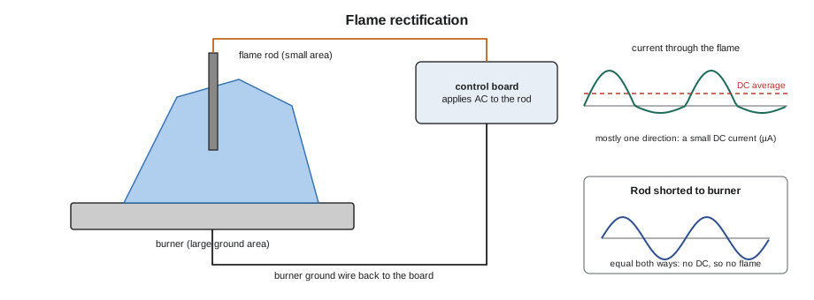
A flame does more than conduct. Because the positive ions are heavy and slow and the electrons are light and quick, and because the two conductors touch the flame over very different areas, the flame conducts much more easily in one direction than in the other. It behaves like a diode, a one-way valve for current, and turns part of an applied AC voltage into a DC current. This is rectification. The large conductor is the burner ground: the burner and its surroundings that are in contact with the flame, connected to the board's ground. The small conductor is the flame sensor or flame rod. The burner ground's area in the flame must be several times the rod's, commonly at least about four times, for the rectifying effect to be strong; the maker sets the rod's position to achieve this.
How the board uses rectification
The control board or ignition module applies an AC voltage to the flame rod, typically a few tens to around a hundred volts, through a high resistance, so that the available current is tiny. With no flame, no current flows. With a flame, the flame's rectifying effect lets a small DC current flow from the rod through the flame to the burner and back to the board through its ground connection. The board's circuit looks specifically for that DC current. If it is above the board's threshold, the board treats the flame as proved; if it falls below, the board treats the flame as lost.
This design is fail-safe in an important way. If the rod is shorted to the burner, through a cracked insulator, a bent rod touching metal or water on the insulator, the AC flows equally in both directions and there is no DC component, so the board does not see a flame. A shorted rod therefore produces a no-flame lockout, never a false flame. Most failures of the rod, its wire and its ground reduce or remove the DC signal and shut the burner down. The one condition the board must guard against separately is a flame signal when there should be none, such as a flame that stays lit after the valve has closed, or a leaking valve; most boards check for this and flash a code for it.
Rectification also responds quickly. A thermocouple must cool before its voltage falls, but the flame's ions vanish the moment the flame does. The control's flame failure response time, given in its specification, is commonly about a second or two: the time from losing the flame to closing the gas valve. Product standards set limits on it.
What a flame signal should be
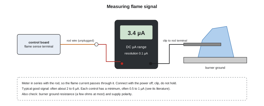
Flame signal is measured in DC microamps. Typical readings depend heavily on the appliance and the control, but on residential furnaces and modules a good signal is often somewhere around 2 to 6 microamps, and many controls accept anything from about 0.5 or 1 microamp up to around 10. Each board has a minimum below which it will not prove flame, given in the appliance or control literature, and a healthy installation runs well above it. A reading only slightly above the minimum is a callback waiting to happen, because flame signal falls as the rod ages and in cold or windy weather.
Some boards and modules display the flame signal on a screen or through a service tool, or provide test pins whose DC voltage stands for it, with the conversion given in the literature. Where they do not, the technician measures it directly.
Measuring the flame signal
Flame current is measured with the meter in series with the flame rod, so that the flame current passes through the meter. The meter must have a DC microamp range with a resolution of at least 0.1 microamp; many ordinary meters have one, and many clamp meters do not. With the power off, the wire is unplugged from the flame rod terminal. One meter lead is connected to the wire, the other to the rod's terminal, using alligator clips or the adapter the meter maker supplies, so that nothing is held by hand while the burner runs. The meter is set to DC microamps, the power is restored, the furnace is started, and the reading is taken once the burner is lit and stable. A reading that swings wildly suggests a loose connection or a flame that is lifting or wavering on the rod.
Two other measurements belong with the flame signal. The first is the burner ground: with the power off, the resistance from the burner to the board's ground terminal, or to the neutral, should be very low, a few ohms at most and preferably much less. The second is polarity and the neutral-to-ground voltage at the furnace supply. Flame sensing circuits reference the board's ground, which is bonded to the neutral at the service; if the hot and neutral are reversed, or the neutral is not bonded to ground on the supply feeding the furnace, the flame circuit loses its reference and the signal becomes weak, erratic or impossible to read. Many boards detect reversed polarity and lock out with a code.
Worked problem
Is the ground area enough?
A flame rod is 1/4 inch in diameter, and 1 inch of its length sits in the flame. The burner surfaces touched by the same flame have an area of about 3.9 square inches. The maker wants a ground area at least four times the rod area in the flame. Is the ratio met?
Show solution
- The rod area in the flame is the curved surface of a cylinder:
- \[\pi d L = \pi \times 0.25 \times 1 \approx 0.785 \text{ in}^2\]
- Ratio of ground area to rod area:
- \[\frac{3.9}{0.785} \approx 5.0\]
Answer: The ratio is about 5, above the minimum of 4. If the rod were pushed farther into the flame, its area would rise and the ratio would fall, weakening the signal. That is one reason the rod is never bent or repositioned to "get more flame on it" without the maker's guidance.
Why flame signal gets weak
A weak or lost flame signal has a short list of causes, and they fall into three groups. The first is the rod itself. Over time a rod collects a thin, hard, whitish or brown coating, mostly oxides and silica from dust, drywall and other contaminants drawn in with the combustion air, and the coating insulates it from the flame. Rods also crack at the ceramic insulator, bend out of the flame, or wear thin and pitted. The second is the flame: a flame that is too small, too lean, lifting or blown away from the rod by a draft or a disturbed burner touches the rod poorly. A flame starved of air or burning with the wrong pressure carries fewer ions where the rod is. The third is the circuit: a loose or corroded rod wire, a wire routed alongside an ignition cable, a poor burner ground, reversed polarity, or a supply with no proper neutral-to-ground reference, as on some portable generators and on some isolated or floating supplies.
Cleaning a dirty rod is a routine service task, but it is done gently. Makers and experienced technicians generally recommend a very fine abrasive pad or very fine steel wool, followed by wiping the rod clean. Emery cloth and sandpaper are best avoided, because they can leave grit on the rod that bakes on and makes the coating worse. The rod is never bent to clean it, and after cleaning it goes back in exactly the position it came from. A rod that is pitted, thin or cracked at its insulator is replaced. The burner's ground surfaces in the flame, and the ground wire's connections, are cleaned too, because a ground coated with rust or paint is as bad as a dirty rod.
Worked problem
Before and after a cleaning
On a maintenance visit, Jonah measures 0.7 µA of flame signal on a furnace whose board literature gives a minimum of 0.5 µA. After cleaning the rod and the burner ground surface and tightening the ground screw, he measures 3.4 µA. How much margin above the minimum did the furnace have before, and how much does it have now?
Show solution
- Margin before, as a ratio of the minimum:
- \[\frac{0.7}{0.5} = 1.4\]
- Margin after:
- \[\frac{3.4}{0.5} = 6.8\]
Answer: Before the cleaning, the signal was only 1.4 times the minimum, so a cold, windy morning or a little more coating would have caused nuisance lockouts. After cleaning it is nearly seven times the minimum. Jonah records both readings on the service sheet, so the next technician can see how fast this rod coats over.
Polarity on Olde Towne East
At the basement apartment, Rosa started with the supply. With her meter on AC volts at the furnace's power terminals, she measured about 120 volts from the wire on the board's hot terminal to ground, but almost nothing from the wire on the neutral terminal to ground, and 120 volts from the neutral-terminal wire to the hot-terminal wire. That was the right total voltage the wrong way round: the wire on the board's neutral terminal was the hot, and the wire on its hot terminal was the neutral. The renovation's electrician had installed a new disconnect switch for the furnace and reversed the two conductors at it. The board's flame circuit, referenced to a ground that now sat 120 volts away from its own neutral connection, could not read the flame properly, and its polarity check was flashing a warning that nobody had read.
In Columbus, the furnace's supply circuit and disconnect are electrical work for a licensed electrical contractor under the electrical permit process, and Bayline's company rule is that its gas technicians do not alter them, as GAS-130 explained. Rosa shut the furnace off at the disconnect, left the tenant two electric heaters with the landlord's permission, and called Bayline's electrical partner, who came the same afternoon, corrected the conductors at the disconnect and confirmed the polarity. Rosa then restarted the furnace and measured a flame signal of 3.1 microamps.
The furnace ran ten cycles without a fault. Rosa had Jonah clear the board's fault history and write the readings on the service report, then showed the landlord the fault chart on the furnace door. "It told everybody what was wrong," she said. "Nobody looked."
Flame signal is also part of every start-up. Not quite three weeks later, when the condensing furnace at the new house on Fairhaven Court was first fired on Thursday, November 12, Jonah measured its flame signal before he did anything else: 3.6 microamps, steady. That number went on the start-up sheet beside the pressures and the temperature rise, so that the first annual service has something to compare against.
Common mistakes
MistakeMeasuring flame current with the meter in parallel with the rod.
InsteadPut the meter in series with the rod, on DC microamps.
MistakeCleaning a flame rod with emery cloth or sandpaper.
InsteadUse a very fine abrasive pad or steel wool and wipe it clean.
MistakeBending the rod farther into the flame to raise the signal.
InsteadLeave it in the maker's position; check the flame, ground and circuit.
MistakeIgnoring a polarity code on the board.
InsteadCheck hot, neutral and ground at the supply; on Bayline's jobs its electrical partner corrects it.
MistakeAccepting a flame signal just above the minimum.
InsteadFind out why it is low; a marginal signal causes intermittent lockouts.
Summary and key terms
- A flame contains ions and conducts weakly, and because the burner ground touches the flame over a much larger area than the rod, the flame conducts mainly one way: it rectifies.
- The board applies AC to the rod and looks for the resulting DC current, in microamps.
- A shorted rod passes AC both ways and gives no DC, so it cannot fake a flame.
- Rectification responds within a second or two.
- Typical good signals are often 2 to 6 µA, and each control has a minimum, often 0.5 to 1 µA.
- Measure in series with the rod on DC microamps, and check the burner ground and the supply polarity.
- Weak signals come from a coated, cracked or misplaced rod, a poor flame, or a poor ground, loose wire, reversed polarity or floating neutral.
- Clean rods gently with a fine pad, never bend them, and record the flame signal on every start-up and service.
- Flame rectification
- The one-way conduction of current through a flame, used to prove that a flame is present.
- Ion
- An electrically charged particle; a flame contains positive ions and free electrons.
- Flame rod
- A metal rod in the flame, insulated from the burner, used as the small electrode for rectification.
- Burner ground
- The grounded burner surfaces in contact with the flame, the large electrode for rectification.
- Microamp (µA)
- One millionth of an amp; the unit of flame signal.
- Flame failure response time
- The time a control takes to close the gas valve after the flame is lost.
- Polarity
- The correct connection of the hot and neutral conductors.
Practice problems
Work each problem on paper first, then reveal the answer to check.
Why can a shorted flame rod not fool the board into seeing a flame?
Show answer
A short passes AC equally both ways, with no DC component.
How is a flame signal measured?
Show answer
With the meter in series with the rod, on the DC microamp range.
What is a typical good flame signal on a residential furnace?
Show answer
Often about 2 to 6 microamps, well above the control's minimum.
Why should emery cloth not be used on a flame rod?
Show answer
It can leave grit that bakes onto the rod and insulates it.
What two supply checks belong with a flame signal measurement?
Show answer
Polarity and the neutral-to-ground reference, plus a low burner ground resistance.
Lesson quiz · 5 questions
Score 60% or more to complete this lesson.
Create a free account to save your progress, take quizzes and earn a certificate.