
ENGG-160 · Lesson 6 of 12 · 27 min
Sketching, 3D CAD and parametric modeling
Lesson 3 explained how to read and produce formal engineering drawings. Before a drawing exists, though, a design lives in sketches and, increasingly, in three-dimensional computer models. Engineers sketch to think, to explore ideas quickly and to explain them to colleagues at a whiteboard or on a job site; they build 3D models to define shapes exactly, check that parts fit, calculate mass and strength, generate drawings and drive manufacturing machines. This lesson covers freehand sketching techniques and why they still matter, the main kinds of CAD software, how parametric solid modeling works and how to capture design intent, assemblies, the exchange of models between programs, and the cautions that apply to simulation results. A short code example shows how a parametric model becomes a design table that explores many versions of a part at once.
Why sketch?
In an age of CAD, freehand sketching might seem obsolete. It is not. Sketching is the fastest way to externalize an idea, and research on designers shows that sketching and thinking are intertwined: drawing a concept reveals problems and suggests alternatives that would not occur to someone working only in their head. A sketch can be made in seconds, anywhere, and invites discussion because it looks unfinished. Experienced engineers sketch in design meetings, in the field to record what they see, in notebooks while working out calculations, and on the back of drawings to explain a change to a contractor. In the concept generation stage of Lesson 1, dozens of rough sketches are worth more than one polished model.
Good engineering sketches are clear rather than artistic. Draw lightly first, then darken the lines that matter. Use simple construction methods; label key features and dimensions; add notes and arrows freely; and do not erase, since earlier lines often contain useful thinking. A sketch should communicate the idea to someone else without your being there to explain it.
Sketching techniques
A few techniques cover most needs:
- Orthographic sketches: front, top and side views, aligned as in Lesson 3, drawn freehand on grid or plain paper. They are the best way to record dimensions and details.
- Isometric sketches: the three axes drawn at 120° to one another, vertical lines vertical and the other two at 30° to the horizontal. Measurements along the axes are true lengths, which makes isometric sketches easy to draw to approximate scale. Isometric grid paper helps.
- Oblique sketches: the front face drawn true shape and the depth drawn at an angle, often 45°, at half length. They are quick for objects with circular or detailed front faces.
- Perspective sketches: parallel lines converging toward one or two vanishing points, as the eye sees them. They look most realistic and are used for presenting concepts to clients and users.
For complex objects, start with a crate, a box enclosing the whole object, and carve away or add to it. Circles in isometric views become ellipses; sketch them inside an isometric square (a rhombus) that touches the ellipse at the midpoints of its sides. Shading and line weight, with thick lines for outside edges and thin for interior edges, make sketches easier to read.
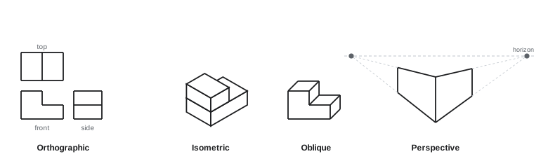
Spatial visualization, the ability to imagine objects in three dimensions and rotate them mentally, is a skill that improves with practice. Students who struggle with it at first typically improve markedly with a few weeks of sketching exercises, and stronger visualization skills are associated with success in engineering programs. Practice by sketching everyday objects from different viewpoints and by converting between orthographic and isometric views.
Kinds of CAD
Computer-aided design (CAD) software ranges from simple drafting tools to complete product lifecycle systems:
- 2D drafting software reproduces the drawing board: lines, arcs and text placed on a sheet. It remains common for building plans, electrical schematics, site layouts and simple parts.
- 3D solid modeling, used for most mechanical design, represents parts as closed volumes, so the software can compute mass, center of gravity and moments of inertia (ENGG-130), detect interference between parts, and generate drawings, toolpaths and simulation meshes.
- Surface modeling describes complex free-form shapes, such as car bodies, aircraft skins and consumer products, as smooth surfaces.
- Building information modeling (BIM), introduced in Lesson 3, models buildings and infrastructure as objects (walls, beams, ducts) carrying data such as materials, fire ratings and costs, coordinated between disciplines.
- Mesh models, collections of triangles, come from 3D scanning and are used for 3D printing and visualization; they describe shape but not design intent.
Each industry has favored tools, and engineers often learn several over a career. The underlying concepts below transfer between them.
Parametric solid modeling
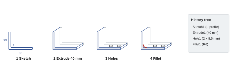
Most mechanical CAD programs build parts by parametric, feature-based modeling. The designer creates a 2D sketch on a plane, defines its shape exactly with dimensions and geometric constraints (horizontal, perpendicular, tangent, equal, concentric, symmetric), and turns it into a solid with a feature: an extrusion, a revolve, a sweep along a path or a loft between profiles. Further features add or remove material: holes, cuts, fillets, chamfers, shells, ribs and patterns. The software records every sketch, dimension and feature in a history tree, so changing a dimension updates the whole part.
A sketch is fully defined when its dimensions and constraints fix every line and point; an underdefined sketch can change shape unexpectedly when something else is edited, and an overdefined one has conflicting constraints. Good practice is to fully define every sketch, keep sketches simple, and build complex shapes from several simple features rather than one complicated sketch.
Design intent
Two models of a part can look identical yet behave very differently when changed. Design intent is the set of decisions about how a part should respond to change, and a skilled modeler builds it into the model. If two holes must always stay centered on a plate, they should be dimensioned from the centerline or constrained symmetric, not dimensioned from one edge. If a wall must always be 3 mm thick, use a shell feature with a thickness parameter rather than separate sketches. If a bracket's holes must match a standard bolt pattern, link their spacing to a single named parameter.
Worked problem
Capturing design intent
A mounting plate 120 mm long has two holes that must stay 20 mm from each end and remain centered top to bottom, because they align with rails whose spacing changes between product sizes. How should the holes be dimensioned in the CAD sketch?
Show solution
- Constrain each hole's center on the horizontal centerline of the plate (a midpoint or symmetric constraint), so changing the plate height keeps them centered.
- Dimension each hole 20 mm from its own end, not from the other hole or from one end only.
- Make the plate length a named parameter (for example, L = 120), so that changing it to 160 moves the second hole with the end.
Answer: Dimensioned this way, the model updates correctly for every product size. Had the second hole been dimensioned 80 mm from the first, lengthening the plate would leave it in the wrong place, and every size would need manual fixing. The same thinking applies to drawings (Lesson 3): dimension features from the datums that matter for function and assembly.
Named parameters and equations let a single model represent a whole family of parts. A design table, a spreadsheet of parameter values, can generate dozens of configurations, such as different lengths, thicknesses or hole patterns, from one model. The same idea can be explored outside CAD with a short script.
import math

# Design table for a parametric 6061 alloy L-bracket: legs 80 mm and 60 mm, width 40 mm,
# two 8.5 mm bolt holes in the long leg, 500 N load at the tip of the short leg
L1, L2, b, d_hole, F = 80.0, 60.0, 40.0, 8.5, 500.0
rho = 2.70e-3            # g per mm3 (6061 alloy)
allow = 100.0            # allowable bending stress, MPa

print("  t (mm)   mass (g)   stress (MPa)   OK?")
for t in [3, 4, 5, 6, 7, 8]:
    volume = (L1 + L2 - t) * b * t - 2 * math.pi * (d_hole / 2) ** 2 * t   # mm3
    M = F * L2                                   # moment at the bend, N mm
    sigma = 6 * M / (b * t ** 2)                 # rectangle: S = b t^2 / 6
    ok = "yes" if sigma <= allow else "no"
print(f"{t:7d} {volume * rho:10.1f} {sigma:13.1f} {ok}") t (mm) mass (g) stress (MPa) OK?
3 43.5 500.0 no
4 57.5 281.2 no
5 71.4 180.0 no
6 85.0 125.0 no
7 98.4 91.8 yes
8 111.6 70.3 yesThe table shows the trade-off a designer faces: each extra millimeter of thickness adds about 13 g, while the bending stress falls with the square of the thickness. The lightest bracket that meets the 100 MPa allowable stress is 7 mm thick. In a real design the stress estimate would be checked more carefully, perhaps with a finite element analysis, but the table identifies the right neighborhood quickly and shows how sensitive the result is to the parameter.
Assemblies
Products are assemblies of parts. In CAD, parts are placed in an assembly and positioned with mates or constraints: this face coincident with that face, this hole concentric with that shaft, this edge parallel to that one. A fully constrained assembly can be moved through its range of motion to check clearances and mechanisms, and an interference check finds places where parts overlap. Assemblies are organized as hierarchies of subassemblies that mirror how the product will be built and maintained.
Assemblies also generate the bill of materials (BOM), the list of every part, its number, material and quantity, which drives purchasing and manufacturing. Standard parts such as fasteners, bearings and motors are usually inserted from libraries or downloaded from suppliers, rather than modeled from scratch.
Top-down design builds parts in the context of the assembly, so that a change to one part (moving a mounting hole in a frame) automatically updates the parts that must match it. It is powerful but creates dependencies that must be managed carefully on large projects.
Exchanging and managing models
Engineers constantly exchange models with suppliers, manufacturers and other disciplines, often using different software. Neutral formats make this possible:
| Format | What it carries | Typical use |
|---|---|---|
| STEP (.stp) | Exact 3D solid geometry | Exchanging mechanical parts between CAD systems |
| IGES (.igs) | Surfaces and curves (older) | Legacy exchange, surface models |
| STL, 3MF | Triangle mesh | 3D printing |
| DWG, DXF | 2D (and some 3D) drafting geometry | Drawings, laser and waterjet cutting |
| IFC | Building objects and data | Exchanging BIM models |
| Drawings as fixed documents | Issuing drawings for review and record |
Neutral formats carry the geometry but usually lose the feature history and design intent, so the receiver gets a "dumb" solid that is hard to modify. Agree on formats, units and coordinate systems with partners at the start of a project; mismatched units between files are a classic source of parts that arrive ten or twenty-five times too large.
On team projects, models change constantly, and several people may need the same file. Product data management (PDM) systems control check-in and check-out, revision numbers and approval workflows, so that everyone works on the current version and released designs cannot be changed without approval. Even on a student project, a shared folder with clear file naming, revision letters and a rule that only one person edits a file at a time prevents painful losses.
Simulation: powerful but not automatic
Many CAD systems include simulation tools: finite element analysis (FEA) for stress and deflection, computational fluid dynamics (CFD) for flow and heat transfer, and motion analysis for mechanisms. They can show stress concentrations and flow patterns that hand calculations miss, and they let designers compare options quickly. But simulation is only as good as its inputs. The loads, supports, material properties and mesh must represent reality; an unrealistic fixed support or a missing load produces colorful, convincing and wrong results.
Good practice is to estimate the answer by hand first (as in the code above or with ENGG-130 methods), check that the simulation agrees in simple regions, refine the mesh until results stop changing at critical points, interpret singular stresses at sharp corners and point supports with care, and have critical analyses reviewed. Simulation supplements engineering judgment; it does not replace it.
From model to manufacture
The 3D model increasingly drives manufacturing directly: computer-aided manufacturing (CAM) software generates toolpaths for CNC machining from the model, 3D printers slice it into layers, and sheet-metal parts are unfolded into flat patterns for laser cutting and bending. In some industries the model with its embedded dimensions and tolerances (model-based definition) is becoming the official record in place of 2D drawings. Lesson 7 looks at how the choice of manufacturing process should shape the design itself.
Common mistakes
MistakeSkipping sketching and starting in CAD.
InsteadSketch many concepts quickly first; model the promising ones.
MistakeLeaving CAD sketches underdefined.
InsteadFully define sketches with dimensions and constraints.
MistakeDimensioning features in whatever way is convenient.
InsteadCapture design intent: dimension from the references that matter functionally.
MistakeExchanging models without agreeing on units and formats.
InsteadAgree on format, units and coordinates at the start.
MistakeAccepting simulation results because they look convincing.
InsteadCheck inputs, compare with hand estimates and refine the mesh.
Summary and key terms
- Sketching is the fastest way to think through and communicate ideas.
- Orthographic, isometric, oblique and perspective sketches suit different purposes; start complex shapes with a crate.
- CAD includes 2D drafting, 3D solids, surfaces, BIM and meshes.
- Parametric modeling builds parts from fully defined sketches and features recorded in a history tree.
- Design intent decides how a model responds to change; parameters and design tables create part families.
- Assemblies use mates, check interference and generate bills of materials; neutral formats lose history.
- Simulation needs realistic inputs and hand checks.
- Isometric sketch
- A pictorial sketch with axes at 120° and true lengths along them.
- Oblique sketch
- A sketch with a true-shape front face and depth drawn at an angle.
- Crating
- Starting a sketch with a box that encloses the whole object.
- Parametric modeling
- CAD modeling driven by editable dimensions and constraints.
- Feature
- An operation such as an extrusion, hole or fillet that builds a solid.
- Fully defined sketch
- A sketch whose geometry is completely fixed by dimensions and constraints.
- Design intent
- The planned way a model should respond to changes.
- Mate
- A constraint positioning parts relative to one another in an assembly.
- Bill of materials
- A list of all parts and quantities in an assembly.
- STEP
- A neutral file format for exchanging exact 3D solid geometry.
Practice problems
Work each problem on paper first, then reveal the answer to check.
Name two situations where a freehand sketch is better than a CAD model.
Show answer
For example: exploring many concepts quickly; recording conditions in the field; explaining an idea in a meeting.
In an isometric sketch, at what angles to the horizontal are the two non-vertical axes drawn?
Show answer
30°.
What does a circle on the face of a cube look like in an isometric sketch?
Show answer
An ellipse inscribed in a rhombus.
What is the difference between a constraint and a dimension in a CAD sketch?
Show answer
A constraint fixes a geometric relationship (parallel, tangent); a dimension fixes a size or distance.
Why should sketches be fully defined?
Show answer
So they cannot change shape unexpectedly when other features are edited.
A shaft must always pass through the center of a housing whose size varies. How should its hole be located?
Show answer
Constrain it to the housing's center (midpoint or symmetric constraints), not by dimensions from one edge.
From the design table, what is the lightest acceptable bracket and its mass?
Show answer
7 mm, about 98 g.
What would the stress be at t = 6.5 mm?
Show answer
4500/6.5² = 106.5 MPa; still too high.
Which format would you send to a supplier who must machine a part using different CAD software?
Show answer
STEP, plus a PDF drawing with tolerances.
Give two checks to make before trusting an FEA stress result.
Show answer
For example: compare with a hand calculation; check loads and supports; refine the mesh.
Lesson quiz · 5 questions
Score 60% or more to complete this lesson.
Create a free account to save your progress, take quizzes and earn a certificate.