
ELV-210 · Lesson 6 of 12 · 20 min
Three-phase power and transformers
Every elevator Tamsin has worked on is fed with three-phase power. The mainline disconnect has three line terminals, the hoist motor or drive has three power connections, and the controller contains a control transformer that takes two of those lines and steps them down to the 120 V or lower that its relays and boards use. Three-phase power is how almost all commercial buildings receive their electricity, because it delivers more power through less copper than single-phase, and because it makes motors that start and run without any extra help. This lesson explains how three-phase systems are arranged, how to calculate their power and current, why phase rotation matters so much to an elevator, and how transformers change voltage.
Three phases
A three-phase supply is three sine waves of the same voltage and frequency, each shifted a third of a cycle, 120 degrees, from the next. At any instant the three voltages add to zero, and the power delivered to a balanced load is steady rather than pulsing, which is why three-phase motors run smoothly. The three supply conductors are called phases or lines, often labeled L1, L2 and L3 or A, B and C. Many systems also have a neutral conductor connected to the star point of the supply transformer.
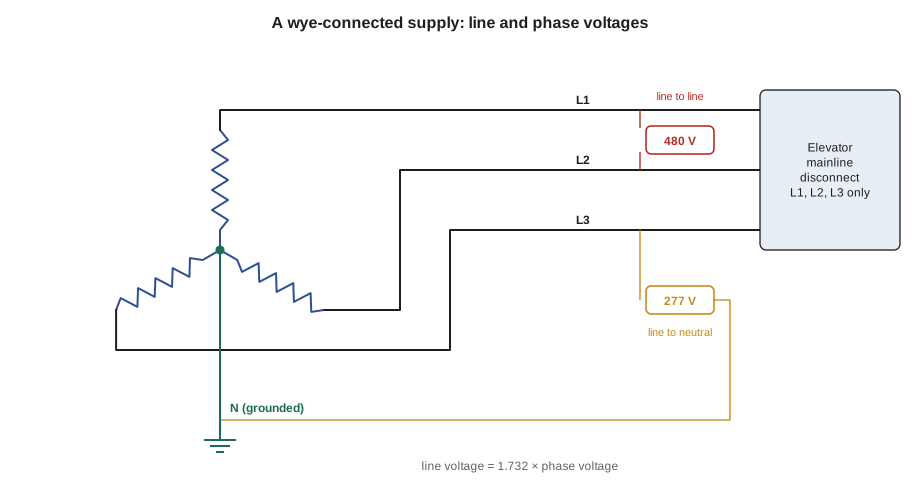
The supply transformer's windings are connected either in wye, also called star, with one end of each winding joined at a common neutral point, or in delta, with the three windings connected end to end in a triangle. In a wye system, the voltage between a line and the neutral, the phase voltage, is smaller than the voltage between two lines, the line voltage, by a factor of the square root of three.
The voltages Tamsin meets follow from that relationship. In Washington, as across most of the United States, larger buildings are commonly fed at 277/480 V wye, as at Quayside Tower: 480 V between lines for motors and elevators, and 277 V from line to neutral for fluorescent and LED lighting. The Tillicum Building has a 480 V supply, and some older buildings still have 240 V delta services. Smaller loads are fed from a 120/208 V wye system through a step-down transformer: 208 V between lines and 120 V to neutral for receptacles.
Power in a three-phase circuit
For a balanced three-phase load, the total power is the square root of three times the line voltage times the line current times the power factor. The formula is used constantly: to find the current a motor draws from its rated power, to size a feeder, or to check whether a measured current makes sense.
For a given power, current falls as voltage rises. That is why the elevator is fed at the highest voltage available: a 480 V feeder carries less current, needs smaller conductors and has less voltage drop than a 208 V feeder for the same motor. The code below compares the Quayside drive's input current at the building's two voltages and checks the voltage drop in the feeder from the electrical room to the control space at the top of the building.
# Quayside car 2 drive input: current and feeder voltage drop (illustrative)
import math
p_in = 32.0e3            # W drawn from the supply at full-load up run
pf = 0.95                # drive input power factor
for v in (480.0, 208.0):
    i = p_in / (math.sqrt(3) * v * pf)
    print(f"at {v:5.0f} V the drive draws {i:5.1f} A per line")
v = 480.0
i = p_in / (math.sqrt(3) * v * pf)
length = 360           # one-way feeder length, ft
r_per = 0.25           # ohms per 1,000 ft per conductor
r = length * r_per / 1000
drop = math.sqrt(3) * i * r * pf        # approximate line-to-line drop
print(f"feeder resistance per conductor {r:.3f} ohm")
print(f"voltage drop {drop:.1f} V = {100 * drop / v:.2f} % of {v:.0f} V")at 480 V the drive draws 40.5 A per line at 208 V the drive draws 93.5 A per line feeder resistance per conductor 0.090 ohm voltage drop 6.0 V = 1.25 % of 480 V
The approximate drop formula treats the feeder as a resistance and ignores its reactance, which is acceptable for a quick check. The electrical code sets limits on voltage drop in feeders and branch circuits, and the elevator manufacturer specifies the range of supply voltage its drive will accept, often plus or minus ten percent. A drop of more than a few percent at full load, added to normal utility variation, can cause nuisance trips on a long up run.
Phase rotation
The order in which the three phases reach their peaks is the phase rotation or phase sequence: L1, L2, L3 or the reverse. A three-phase induction motor turns in a direction set by the rotation. Swap any two of the three supply conductors and the motor reverses. For a hydraulic pump this reverses the pump, which may then fail to build pressure or be damaged. For a traction elevator with an across-the-line or two-speed motor, reversed rotation would make the car travel in the opposite direction to the one the controller commanded, which could drive the car into a terminal landing.
The codes therefore require protection against reversal and loss of phase for elevators whose motors could be affected. Controllers have a phase monitor, a relay or a function of the drive that checks the sequence and the presence of all three phases and opens the safety circuit if either is wrong. Utility work, a transformer replacement or a rewiring in the electrical room can reverse the rotation without anyone in the building knowing. Ray checks the rotation with a phase rotation meter whenever the supply has been worked on, and he never moves the phase monitor connections to make a nuisance trip go away.
Loss of one phase, often called single phasing, is a related hazard. A blown fuse on one line or a loose connection at the disconnect leaves a three-phase motor running on two lines. A running motor may keep turning but draws much higher current in the remaining conductors and overheats; a stopped motor will not start and hums. Drives detect it as an input phase loss and fault. On older relay controllers the phase monitor is the protection.
# Voltage unbalance at the Tillicum controller from three line-to-line readings
readings = {"L1-L2": 478.0, "L2-L3": 466.0, "L3-L1": 482.0}
avg = sum(readings.values()) / 3
worst = max(abs(v - avg) for v in readings.values())
unbalance = 100 * worst / avg
print(f"average {avg:.1f} V, largest deviation {worst:.1f} V, unbalance {unbalance:.2f} %")
# a common rule of thumb: motor heating rises by about 2 x (unbalance %) squared percent
print(f"approximate added motor heating: {2 * unbalance ** 2:.0f} %")
print("investigate" if unbalance > 2.0 else "acceptable")average 475.3 V, largest deviation 9.3 V, unbalance 1.96 % approximate added motor heating: 8 % acceptable
A small voltage unbalance causes a much larger current unbalance in an induction motor and extra heating, so a reading of more than two percent is worth chasing, usually back to a loose connection or a heavily loaded single-phase circuit elsewhere in the building.
Transformers
A transformer is two or more coils wound on a shared iron core. An alternating current in the primary winding creates an alternating magnetic flux in the core, and the flux induces a voltage in the secondary winding. The voltage in each winding is proportional to its number of turns, so the ratio of the voltages equals the ratio of the turns. A transformer works only on AC, because only a changing flux induces a voltage.
Ignoring small losses, the power in equals the power out, so when a transformer steps the voltage down, it steps the current up by the same ratio. Transformers are rated in volt-amperes, not watts, because their heating depends on the current whatever the power factor of the load.
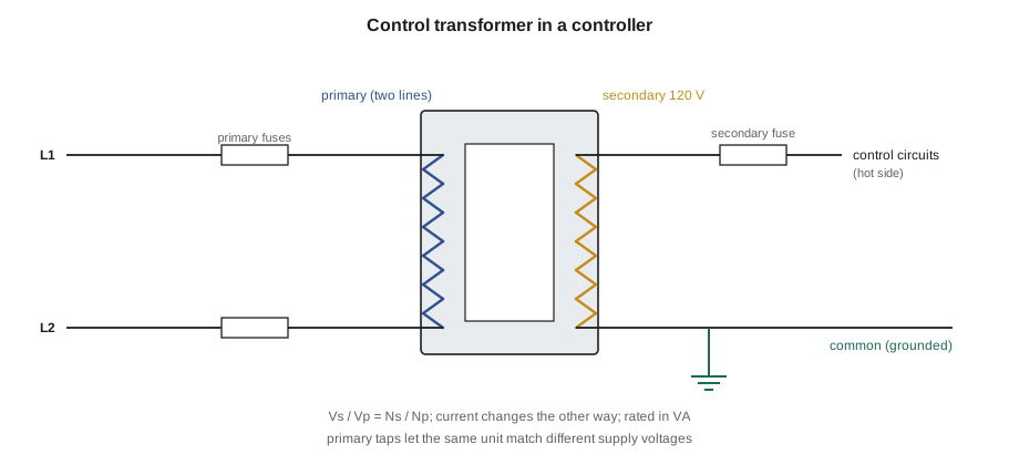
The control transformer in an elevator controller takes two lines of the supply on its primary and provides 120 V, or sometimes 110 V or 24 V, on its secondary for the relays, contactors and boards. It isolates the control circuit from the power supply and lets one side of the secondary be grounded, which gives the predictable fault behavior described in Lesson 3. Both sides are fused: the primary fuses protect the transformer and its supply wiring, and the secondary fuse protects the control circuit wiring.
# Sizing check for the Tillicum car 1 control transformer
v_p, v_s = 480.0, 120.0
rating_va = 500.0
loads_va = {"relay coils (holding)": 180.0, "contactor coils (holding)": 110.0,
            "signal and lamp circuits": 70.0, "door operator control": 40.0}
inrush_va = 900.0       # brief demand while the main contactors pick up
total = sum(loads_va.values())
ratio = v_p / v_s
print(f"turns ratio {ratio:.1f}:1")
print(f"steady load {total:.0f} VA = {100 * total / rating_va:.0f} % of rating")
print(f"secondary current {total / v_s:.2f} A, primary current {total / v_p:.2f} A")
print(f"inrush demand {total + inrush_va:.0f} VA for a fraction of a second")turns ratio 4.0:1 steady load 400 VA = 80 % of rating secondary current 3.33 A, primary current 0.83 A inrush demand 1300 VA for a fraction of a second
A control transformer runs well within its rating in steady service, but it must also supply the brief inrush of the AC contactor coils described in Lesson 5. Transformers for control service are rated for a short-time inrush as well as their continuous rating. When a contactor chatters or drops out as the car starts, one possible cause is a transformer whose output voltage sags under that inrush, perhaps because a load has been added since it was sized, or because its primary is wired to the wrong voltage tap.
Most control transformers have several primary taps, for example for 480, 575 and 600 V, or for 208, 240 and 480 V, so that the same unit can be used on different supplies. If a building's supply is lower than the tap connected, the secondary is lower than 120 V in proportion. On an old building where the supply is consistently low, the tap is moved to match, by a qualified person with the power locked out.
Worked problem
A low control voltage at Tillicum
Car 1 at the Tillicum Building has been dropping out on starts in the morning. Ray measures 470 V between lines at the controller and 112 V at the control transformer secondary with the car idle. The transformer primary is connected to its 480 V tap. What is happening, and what is the expected secondary voltage?
Show solution
- The ratio is 480:120, or 4:1. At 470 V on the primary the secondary should be 470 / 4 = 117.5 V with the car idle.
- The measured 112 V is about 5 V lower than the ratio predicts, with only a light load, so something between the primary terminals and the secondary terminals is dropping voltage, or the transformer itself is faulty.
- With the power locked out, Ray finds the primary fuse clips loose and discolored, adding resistance in the primary circuit.
- He replaces the fuse holder, and the secondary then reads 117 V idle and 113 V during contactor pickup, which is within the relays' range.
Answer: The fault was a resistive primary fuse clip; the transformer ratio told Ray what the secondary should read.
Grounding and bonding
Every metal enclosure in an elevator installation, from the controller cabinet and the machine frame to the rails, the car frame and the hoistway door frames, is bonded to the building's grounding system. Bonding connects them together and to ground with conductors of low resistance, so that if a live conductor touches the metal, a large fault current flows, the protective device opens quickly, and the metal does not stay at a dangerous voltage while someone is touching it. The equipment bonding conductor runs with the circuit conductors in the feeder and in the traveling cable, and the code sets its size. A missing or loose bond is invisible in normal service, which is why Ray checks the bonding jumpers on the machine and the controller whenever equipment has been removed or replaced.
Bonding is also what makes the grounded control circuits of Lesson 3 work. The grounded side of the control transformer secondary is connected to the same grounding system, so a ground fault on the live side has a low-resistance path back to the transformer and clears the fuse. If the bond between the controller and the car frame is lost, a ground fault on the car may not clear, and the car frame can sit at a hazardous voltage until someone touches it and a grounded rail at the same time.
Common mistakes
MistakeSwapping two motor leads to fix a direction problem without checking the supply rotation.
InsteadFind out why the rotation changed; the phase monitor and the controller depend on it.
MistakeMoving phase monitor wires to stop nuisance trips.
InsteadA phase monitor trip means a phase is missing, low or reversed; find the cause.
MistakeCalculating three-phase current without the square root of three.
InsteadI = P / (√3 × V × pf).
MistakeAssuming a transformer works on DC.
InsteadOnly changing flux induces a voltage; a transformer on DC is a short circuit through its winding.
MistakeIgnoring a low secondary voltage because the car still runs.
InsteadLow control voltage leads to dropouts and burnt coils; compare the reading with the turns ratio.
Summary and key terms
- Three-phase power uses three sine waves 120 degrees apart and delivers steady power to balanced loads.
- In a wye system the line voltage is √3 times the phase voltage.
- Three-phase power is √3 × line voltage × line current × power factor.
- Phase rotation sets the direction of an induction motor; elevators are protected against reversal and phase loss.
- Voltage unbalance of a few percent causes much larger current unbalance and heating in motors.
- A transformer changes voltage in proportion to its turns ratio and current in inverse proportion; control transformers are fused on both sides.
- Line voltage
- The voltage between two line conductors of a three-phase system.
- Phase voltage
- The voltage from a line to the neutral point in a wye system.
- Wye connection
- Three windings joined at a common neutral point, also called star.
- Delta connection
- Three windings connected end to end in a closed triangle.
- Phase rotation
- The order in which the three phases reach their peaks.
- Single phasing
- Loss of one phase of a three-phase supply.
- Turns ratio
- The ratio of a transformer's primary and secondary turns, equal to the voltage ratio.
Practice problems
Work each problem on paper first, then reveal the answer to check.
What is the line-to-neutral voltage of a 600 V wye system? Of a 480 V wye system?
Show answer
600 / 1.732 = 346 V (called 347 V); 480 / 1.732 = 277 V.
A 480 V three-phase motor draws 40 A at a power factor of 0.85. What real power does it draw?
Show answer
1.732 × 480 × 40 × 0.85 = 28.3 kW.
A control transformer has a 480 V primary and a 120 V secondary. It supplies 3 A. What current flows in the primary?
Show answer
Ratio 4:1, so 3 / 4 = 0.75 A.
What does a phase monitor do in an elevator controller?
Show answer
It checks that all three phases are present and in the correct sequence, and opens the safety circuit if not.
Lesson quiz · 5 questions
Score 60% or more to complete this lesson.
Create a free account to save your progress, take quizzes and earn a certificate.