
ELV-210 · Lesson 11 of 12 · 20 min
Reading elevator wiring diagrams
Every controller Tamsin opens has a set of drawings with it, usually in a pocket on the inside of the cabinet door or in a binder in the machine room. On the Tillicum relay controllers the drawings are large, folded, yellowed sheets marked up in pencil by several generations of mechanics. On the Quayside controllers they are a bound set of printed pages from the manufacturer, with a separate document for the drive parameters. Ray's view is that a mechanic who cannot read the drawings can only replace parts until the fault goes away, while one who can read them can find the fault. This lesson pulls together everything in the course so far, because a wiring diagram is simply the circuits of Lessons 2 to 10 drawn in a standard way.
Kinds of drawings
An elevator controller usually comes with several kinds of drawing. The schematic, often drawn in ladder form, shows how the circuits work: each circuit is a horizontal line, or rung, between two vertical rails that represent the control supply, with the contacts and coils in the order the current passes through them. It ignores where the parts are physically located. The wiring or connection diagram shows where each wire physically goes, terminal by terminal, inside the controller and out to the hoistway, car and machine. The field wiring or interconnection diagram shows the cables between the controller and the devices in the building, with the conductor numbers in the traveling cable and the hoistway wiring. Layout drawings show where components sit in the cabinet. For troubleshooting, the schematic is where a mechanic thinks and the wiring diagram is where she finds the terminal to put her meter on.
The codes require the wiring diagrams for an elevator to be available on site, and Northcrest's practice is that they stay with the controller. Changes made in the field are marked on the drawings at the time, in ink, dated and initialed, so that the next mechanic sees the equipment as it actually is. Nothing slows a fault call more than a drawing that does not match the wiring.
Symbols
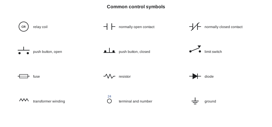
Elevator drawings use the standard symbols of North American control drawings, with some variations between manufacturers. A coil is drawn as a circle or a rectangle with the device designation inside it. A normally open contact is two short parallel lines across the circuit, and a normally closed contact is the same with a diagonal stroke through it. Push buttons, limit switches, pressure switches and temperature switches have their own symbols that show how they are operated. Fuses, resistors, transformers, diodes, terminals and ground connections are drawn as in any electrical drawing. Each manufacturer includes a legend sheet, and the first thing Priya tells the class to read on an unfamiliar set is the legend.
| Designation | Typical meaning | Course link |
|---|---|---|
| SAF, SR or SC | Safety relay or safety circuit input | Lesson 3, the safety string |
| DL, GS | Door lock and car gate switch circuits | Lesson 3, the door lock string |
| U, D | Up and down direction relays or contactors | Lesson 7, interlocks |
| M, MC, PM | Main or motor contactors | Lesson 7, contactor monitoring |
| BK, BR | Brake relay or brake contactor | Lessons 2 and 7, brake coils and suppression |
| INS, ACC | Inspection and access operation | ELV-110, top of car work |
| PH, PMR | Phase monitor relay | Lesson 6, phase rotation |
| FL, FLR | Field loss relay | Lesson 8, DC motors |
Line numbers, wire numbers and cross-references
Ladder schematics number every rung along the left margin, and the numbers are the key to reading them. Next to each coil, on the right margin, is a list of the line numbers where that relay's contacts appear, with normally closed contacts marked, often underlined or with a bar. To understand what a relay does, a mechanic finds its coil, reads its cross-reference list, and looks at each of the lines where its contacts are used. To understand why a relay is not picking up, she reads the rung that feeds its coil from left to right and asks which contact in it is open.
Wire numbers tie the schematic to the real wiring. Every conductor that is electrically the same point has the same number, and the number appears on the drawing and on a marker on the wire at each end. A wire number does not change through a terminal, but it does change through a contact or a coil, because those are points where the voltage can be different. Terminal numbers show where the wire lands on terminal strips. On the field wiring diagram, the same numbers appear on the conductors of the traveling cable and the hoistway wiring, so that a voltage at terminal 24 in the controller can be followed to the same wire number in the car top junction box.
Reading a run circuit
Priya puts a simplified schematic of a relay controller's run circuit on the board, adapted from the Tillicum drawings. It has six rungs between the 120 V control rails.
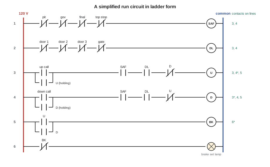
Rung 1 is the safety string, ending in the SAF relay coil. Rung 2 is the door lock string feeding the DL relay. Rung 3 is the up direction circuit: an up demand from the call logic, in parallel with a normally open U contact that holds the relay in, all in series with normally open contacts of SAF and DL and a normally closed contact of D. Rung 4 is the same for down, with a normally closed U contact as the interlock. Rung 5 energizes the brake relay through a U or a D contact in parallel. Rung 6 lights a lamp through a normally closed BK contact, showing that the brake relay has dropped out.
Read as sentences, the rungs say: the car may run up if the safety string is complete, and the doors are locked, and it is not running down, and either there is an up demand or it is already running up. The brake lifts if the car is running in either direction. These are the AND, OR and NOT decisions of Lesson 3 and the holding circuits and interlocks of Lesson 7. The code below simulates the circuit, so the class can open a contact and see which relays drop out.
# Simulating a simplified run circuit, rung by rung
def solve(inputs, state):
    s = dict(state)
    for _ in range(5):                      # repeat until the relays settle
        s["SAF"] = all(inputs["safety"])
        s["DL"] = all(inputs["locks"])
        s["U"] = (inputs["up_demand"] or s["U"]) and s["SAF"] and s["DL"] and not s["D"] and not inputs["stop_up"]
        s["D"] = (inputs["down_demand"] or s["D"]) and s["SAF"] and s["DL"] and not s["U"] and not inputs["stop_down"]
        s["BK"] = s["U"] or s["D"]
    return s

state = {"SAF": False, "DL": False, "U": False, "D": False, "BK": False}
inputs = {"safety": [True] * 8, "locks": [True] * 5, "up_demand": True, "down_demand": False,
          "stop_up": False, "stop_down": False}
state = solve(inputs, state)
print("up call, all closed:   ", {k: int(v) for k, v in state.items()})
inputs["up_demand"] = False                  # call relay drops; U holds itself in
state = solve(inputs, state)
print("demand removed:        ", {k: int(v) for k, v in state.items()})
inputs["locks"][3] = False                   # a hoistway door lock opens
state = solve(inputs, state)
print("door lock 4 opens:     ", {k: int(v) for k, v in state.items()})
inputs["locks"][3] = True
state = solve(inputs, state)
print("lock remade, no demand:", {k: int(v) for k, v in state.items()})up call, all closed: {'SAF': 1, 'DL': 1, 'U': 1, 'D': 0, 'BK': 1}
demand removed: {'SAF': 1, 'DL': 1, 'U': 1, 'D': 0, 'BK': 1}
door lock 4 opens: {'SAF': 1, 'DL': 0, 'U': 0, 'D': 0, 'BK': 0}
lock remade, no demand: {'SAF': 1, 'DL': 1, 'U': 0, 'D': 0, 'BK': 0}The output shows the holding circuit at work: when the up demand is removed, U stays in through its own contact. When a door lock opens, DL drops, U loses its feed and drops, and the brake relay drops with it. When the lock is remade, the car does not restart, because the holding circuit was broken and there is no new demand. That last result is a design feature, not a fault. A car that restarted on its own when a door lock remade would be dangerous.
Troubleshooting from the drawing
The drawing turns a symptom into a list of possibilities. If the car will not run up, the mechanic finds the U coil and reads its rung: the up demand or holding contact, SAF, DL and the normally closed D contact must all be closed. She measures from the right-hand end of the rung, at the coil, to the common rail: if there is 120 V there and the relay is not picking up, the coil is open. If there is no voltage, she works back along the rung, measuring from each contact's terminals to common, until she finds the point where the voltage disappears, exactly the method of Lesson 3. Each measuring point has a wire number on the drawing and on the wire, so the drawing tells her which terminal to probe.
Modern microprocessor controllers change the details but not the method. The logic is in software, but the inputs and outputs are still drawn: the safety string still ends at an input terminal on a safety board, the door locks at another, and the outputs that drive the contactors and brake are shown with their terminal numbers. The controller's diagnostic display shows the state of each input and output, which is the electronic equivalent of watching the relays, and a mechanic compares what the display says with what her meter reads at the corresponding terminal. A disagreement between them, such as an input shown off while the meter reads full voltage at its terminal, points to the board or its connector rather than the field wiring.
# Building a cross-reference from a list of rungs, as a drawing's right margin does
rungs = {
    1: ["safety string", "coil SAF"],
    2: ["door locks", "coil DL"],
    3: ["no up demand | no U", "no SAF", "no DL", "nc D", "coil U"],
    4: ["no down demand | no D", "no SAF", "no DL", "nc U", "coil D"],
    5: ["no U | no D", "coil BK"],
    6: ["nc BK", "lamp brake set"],
}
xref = {}
for line, parts in rungs.items():
    for part in parts:
        for item in part.split("|"):
            kind, *name = item.split()
            if kind in ("no", "nc") and len(name) == 1 and name[0].isupper():
                xref.setdefault(name[0], []).append(f"{line}{'*' if kind == 'nc' else ''}")
for coil in ("SAF", "DL", "U", "D", "BK"):
print(f"{coil:<4} contacts on lines: {', '.join(xref.get(coil, []))} (* = normally closed)")SAF contacts on lines: 3, 4 (* = normally closed) DL contacts on lines: 3, 4 (* = normally closed) U contacts on lines: 3, 4*, 5 (* = normally closed) D contacts on lines: 3*, 4, 5 (* = normally closed) BK contacts on lines: 6* (* = normally closed)
Worked problem
Following a wire number into the hoistway
On the Tillicum car 1 schematic, the door lock string runs from wire 30 at the controller through the five hoistway door interlocks and the car gate switch to wire 37, which feeds the DL relay. With the car at the lobby and the doors closed, DL will not pick up. Tamsin measures 120 V from wire 30 to common and 0 V from wire 37 to common. The field wiring diagram shows the interlocks wired in floor order from the top: floor 6 is between wires 30 and 31, floor 5 between 31 and 32, and so on down to the lobby between 34 and 35, then the car gate between 36 and 37 through the traveling cable. How does she find the open lock without a jumper?
Show solution
- The string is live at 30 and dead at 37, so the open point is somewhere between.
- The hoistway door interlock wires land on a terminal strip in the controller as well as at the doors. Measuring from each terminal to common at the strip, she reads 120 V at 31, 32 and 33 and 0 V at 34.
- The open is between 33 and 34, which the field wiring diagram shows is the floor 2 interlock.
- Ray takes the car to floor 2 on inspection, with the hoistway door closed, and finds the interlock contacts out of adjustment so that they do not make up when the door locks.
Answer: Following the wire numbers on the terminal strip locates the open contact at floor 2 in a few readings, with no jumper and no trip up and down the hoistway.
Common mistakes
MistakeStarting to probe before reading the legend and the rung.
InsteadRead the legend and the rung for the device that is not working first.
MistakeAssuming the wire number changes at a terminal.
InsteadWire numbers change only through contacts, coils and other devices.
MistakeLeaving a field change unmarked on the drawings.
InsteadMark changes in ink on the site drawings, dated and initialed.
MistakeExpecting a car to restart by itself when a lock remakes.
InsteadThe holding circuit is broken by design; a new demand is needed.
MistakeTrusting the diagnostic display over the meter, or the reverse.
InsteadCompare them; a disagreement points to the board or its connector.
Summary and key terms
- Schematics show how circuits work; wiring and field diagrams show where wires physically go.
- Ladder schematics draw each circuit as a rung between control rails, read left to right.
- Line numbers and cross-references show where each relay's contacts are used.
- Wire numbers identify the same electrical point on the drawing and on the wire, changing only through devices.
- A rung reads as a sentence of AND, OR and NOT conditions, with holding contacts and interlocks.
- Troubleshooting follows the voltage along the rung that should be feeding the device that is not working.
- Schematic
- A drawing that shows how a circuit works, without regard to physical layout.
- Ladder diagram
- A schematic with each circuit drawn as a horizontal rung between two supply rails.
- Wiring diagram
- A drawing that shows the physical connections of each wire, terminal by terminal.
- Cross-reference
- The list beside a coil of the line numbers where its contacts appear.
- Wire number
- An identifier given to all conductors that form the same electrical point.
- Legend sheet
- The page that defines a drawing set's symbols and designations.
Practice problems
Work each problem on paper first, then reveal the answer to check.
On a ladder schematic, why are the contacts in a rung read left to right?
Show answer
They are drawn in the order current passes through them from the supply rail to the coil and the common rail.
A relay's cross-reference shows 14, 22* and 37. What does that tell you?
Show answer
It has normally open contacts on lines 14 and 37 and a normally closed contact on line 22.
Wire 52 enters a terminal and leaves to a limit switch. What is the number on the far side of the switch?
Show answer
A different number, because the voltage there can differ when the switch is open.
The display shows an input off, but your meter reads 120 V at its terminal to common. What do you suspect?
Show answer
The input board or its connector, not the field wiring.
Lesson quiz · 5 questions
Score 60% or more to complete this lesson.
Create a free account to save your progress, take quizzes and earn a certificate.