
ELV-210 · Lesson 2 of 12 · 20 min
DC circuits and Ohm's law
Priya Sandhu starts the theory itself with direct current, because DC is where the relationships between voltage, current and resistance are easiest to see, and because elevators are full of it. The safety circuit of a modern controller often runs at 24 or 48 V DC. Brake coils on many traction machines are DC coils fed through a rectifier. Encoders, landing sensors and door operator boards run from DC supplies. The old Tillicum cars on Route 7 have a DC hoist motor fed from a motor-generator set, which Tamsin will meet in Lesson 8. Every one of these is understood with three quantities and one law.
Charge, current, voltage and resistance
Electric current is the flow of electric charge. In a metal wire the charge is carried by electrons, which drift through the copper when a voltage pushes them. Current is measured in amperes: one ampere is one coulomb of charge passing a point every second. Voltage, or potential difference, is the push: the energy given to each coulomb of charge as it moves between two points, measured in volts. One volt is one joule per coulomb. Resistance is the opposition to current, measured in ohms. A long thin wire, a heating element, a lamp filament and a coil of fine wire all have resistance that turns electrical energy into heat.
A useful picture is water in a pipe. Voltage is like the pressure difference that drives the water, current is like the flow rate, and resistance is like a narrow section that restricts the flow. The analogy breaks down in places, but it gets the direction of every relationship right: more push gives more flow, and more restriction gives less.
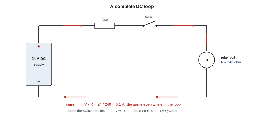
Current only flows in a complete loop. A battery or power supply has two terminals, and current leaves one, passes through the load and returns to the other. Open the loop anywhere, with a switch, a relay contact, a broken wire or a door lock that has not made up, and the current stops everywhere in the loop at once. That single fact is the basis of every elevator safety circuit: dozens of contacts in one loop, any one of which can stop the car.
Ohm's law
For most conductors and resistors, the current is proportional to the voltage across them. The constant of proportionality is the resistance, and the relationship is Ohm's law.
If a relay coil has a resistance of 240 ohms and is connected to 24 V DC, the current through it is 24 / 240 = 0.1 A, or 100 mA. Double the voltage and the current doubles; double the resistance and the current halves. A mechanic uses the law in both directions. Knowing the supply voltage and the measured current, she can work out the resistance of a coil without disconnecting it. Knowing the resistance of a coil from its data sheet and the supply voltage, she can predict the current and choose a fuse.
Ohm's law also explains why a poor connection is a problem. A clean, tight terminal has a resistance of a few thousandths of an ohm. A corroded or loose terminal may have a resistance of an ohm or more. In a circuit carrying a few amperes, that resistance drops several volts across the terminal, leaving less for the load, and it heats the terminal, which oxidizes further and gets worse. A burnt terminal on a brake circuit or a door operator feed is one of the commonest faults Ray finds on older equipment.
Power and energy
Power is the rate at which energy is delivered, measured in watts. In a DC circuit it is the product of voltage and current. Using Ohm's law, it can be written in terms of either one and the resistance.
The three forms answer different questions. The power drawn by a relay coil on a 24 V supply is V times I. The heat produced in a terminal or a wire is I squared times R, which shows why heating rises so quickly with current: double the current through a bad connection and it produces four times the heat. The power in a heating element or a braking resistor connected across a known voltage is V squared over R.
Energy is power multiplied by time, in joules, or in watt-hours for larger amounts. A 60 W cab lighting load running for 24 hours uses 1,440 watt-hours, or 1.44 kWh. Energy matters for battery rescue units, which must hold enough charge to move a car to a landing, and for the heat that a controller cabinet must get rid of.
Resistance of conductors
A conductor's resistance depends on its material, its length and its cross-sectional area. Copper is used for almost all wiring because its resistivity is low. Resistance rises with length, because the charge has further to go, and falls with area, because there is more room for it.
Resistance also rises with temperature: copper's resistance increases by about 0.22 percent for every degree Fahrenheit. A brake coil that measures 100 ohms cold in the morning may measure 120 ohms after a busy day of running, and its current will be correspondingly lower. Coil data sheets usually state the resistance at 68 or 77 °F, and a mechanic who measures a hot coil allows for the difference.
| Conductor size | Approximate resistance of copper at 68 °F | Typical elevator use |
|---|---|---|
| 20 AWG | about 10 ohms per 1,000 ft | Signal and fixture wiring in a traveling cable |
| 18 AWG | about 6.4 ohms per 1,000 ft | Control conductors, door operator feeds |
| 14 AWG | about 2.5 ohms per 1,000 ft | Car lighting circuit, receptacles |
| 8 AWG | about 0.63 ohms per 1,000 ft | Small hoist motor feeders |
Voltage drop in a traveling cable
The traveling cable connects the car to the controller and hangs in a loop below the car. On a high-rise car it is long: at Quayside, with 285 ft of travel and the controller at the top landing, a conductor from the controller to the car top runs well over 300 ft. A circuit to the car uses two conductors, one out and one back, so the loop resistance is twice the resistance of one conductor. When a DC supply in the controller feeds a load on the car, the current through that loop resistance drops voltage, and the car top equipment sees less than the supply.
Priya gives the class a real case. A 24 V DC supply in the Quayside controller feeds the car top inspection station and a landing sensor through 18 AWG conductors. The code below works out the loop resistance, the voltage drop and the voltage at the car for a range of load currents.
# Voltage drop on a DC circuit through the traveling cable
supply = 24.0                 # V DC at the controller
length = 310                # one-way conductor length, ft
r_per = 6.4                # ohms per 1,000 ft of one conductor
r_loop = 2 * length * r_per / 1000   # out and back
print(f"loop resistance: {r_loop:.2f} ohms")
for amps in (0.25, 0.5, 1.0, 2.0):
    drop = amps * r_loop
    at_car = supply - drop
    pct = 100 * drop / supply
    ok = "ok" if at_car >= 21.6 else "too low (below 90 % of 24 V)"
print(f"{amps:4.2f} A: drop {drop:4.2f} V ({pct:4.1f} %), at car {at_car:5.2f} V {ok}")loop resistance: 3.97 ohms 0.25 A: drop 0.99 V ( 4.1 %), at car 23.01 V ok 0.50 A: drop 1.98 V ( 8.3 %), at car 22.02 V ok 1.00 A: drop 3.97 V (16.5 %), at car 20.03 V too low (below 90 % of 24 V) 2.00 A: drop 7.94 V (33.1 %), at car 16.06 V too low (below 90 % of 24 V)
At a quarter of an ampere the drop is small. At two amperes, the car top sees well under 21.6 V, which is below the minimum many sensors and relays are designed for. That is why a controller designer either keeps the car top DC loads small, uses several conductors in parallel, or puts a separate supply on the car. It is also why a voltage reading at the car top is compared with the reading at the controller during troubleshooting: a large difference points to a high-resistance connection somewhere in the cable or its terminals, not to the supply.
Fuses and protection
A fuse or circuit breaker protects the wiring from overcurrent. If a short circuit puts a near-zero resistance across the supply, Ohm's law says the current becomes very large, limited only by the supply and the wiring. The fuse melts and opens the circuit before the wire overheats. Control circuits in an elevator controller are protected by small fuses, often 1 to 10 A, sized to the wire and to the load. A fuse that blows repeatedly is a symptom, never the fault: something downstream is drawing too much current, or there is a short to ground. Replacing it with a larger fuse removes the protection and has started fires.
Ray's habit, when he finds a blown control fuse, is to measure the resistance of the circuit with the power locked out before fitting a new one. A reading near zero ohms from the load side of the fuse to ground or to the other supply conductor tells him there is a short that must be found first. A reading close to the expected resistance of the coils on that circuit tells him the fault may have been intermittent, such as a wire chafing against a moving part, and he looks for it before returning the car to service.
A brake coil on DC
Many traction machines use a DC brake: springs apply the brake shoes or pads, and a coil, when energized, pulls an armature that lifts them. The coil is often energized at a higher voltage to lift the brake quickly and then switched to a lower holding voltage, because once the armature is pulled in, the magnetic circuit needs much less current to hold it. On the Quayside machines the brake controller does this electronically. On older equipment it was done with a resistor switched into the circuit by a contact once the brake had lifted.
# Brake coil: lifting and holding current, power and heat
R_cold = 96.0        # coil resistance at 68 F, ohms
temp = 158.0          # coil temperature after running, F
alpha = 0.00218      # copper temperature coefficient, per F
R_hot = R_cold * (1 + alpha * (temp - 68))
for name, volts in (("lift", 190.0), ("hold", 95.0)):
    for label, r in (("cold", R_cold), ("hot", R_hot)):
        i = volts / r
        print(f"{name} at {volts:5.1f} V, {label}: R {r:6.1f} ohm, I {i:4.2f} A, P {volts * i:5.0f} W")
# economy resistor that gives the holding voltage from the lifting supply
R_econ = R_cold * (190.0 / 95.0 - 1)
print(f"series economy resistor for half voltage: {R_econ:.0f} ohm")lift at 190.0 V, cold: R 96.0 ohm, I 1.98 A, P 376 W lift at 190.0 V, hot: R 114.8 ohm, I 1.65 A, P 314 W hold at 95.0 V, cold: R 96.0 ohm, I 0.99 A, P 94 W hold at 95.0 V, hot: R 114.8 ohm, I 0.83 A, P 79 W series economy resistor for half voltage: 96 ohm
The output shows two things. The holding power is a quarter of the lifting power, because power goes with the square of the voltage, so the coil runs much cooler at the holding voltage. And a hot coil draws noticeably less current than a cold one, which matters when Ray checks a brake current against the manufacturer's figure: he notes whether the machine has just been running.
Worked problem
A slow brake at Tillicum
Car 2 at the Tillicum Building sometimes starts with a jerk, as if the brake drags for a moment. The DC brake coil is rated for 100 V and its data plate gives 64 ohms at 68 °F. With the car running on inspection, Ray measures 100 V at the controller terminals but only 88 V at the coil terminals on the machine. What does that suggest, and what current should the coil draw?
Show solution
- Expected current at the rated voltage: 100 / 64 = 1.56 A (cold).
- The 12 V difference between the controller and the coil is lost in the wiring between them. With about 1.5 A flowing, the resistance in that path is about 12 / 1.5 = 8 ohms, far more than the few tenths of an ohm the wiring should have.
- At 88 V the coil draws less current and produces less pull, so the brake lifts slowly or only partly, which matches the jerk on starting.
- With the power locked out, Ray checks the terminals along the path and finds a discolored, loose lug at the machine junction box.
Answer: A 12 V drop means a high-resistance connection of about 8 ohms in the brake feed; the loose lug is cleaned, replaced and torqued, and the coil voltage rechecked.
Common mistakes
MistakeThinking a loop with one open contact still has current in the rest of the circuit.
InsteadAn open anywhere in a series loop stops the current everywhere in it.
MistakeMeasuring a hot coil and calling it faulty because its resistance is high.
InsteadCorrect for temperature; copper rises about 0.22 % per degree Fahrenheit.
MistakeReplacing a blown fuse with a larger one.
InsteadFind the short or overload first; the fuse protects the wiring.
MistakeForgetting the return conductor in a voltage drop calculation.
InsteadA two-wire circuit has twice the length of one conductor in its loop.
MistakeIgnoring a few volts of difference between controller and load.
InsteadA difference under load points to a high-resistance connection that will heat and get worse.
Summary and key terms
- Current is the flow of charge in amperes, voltage is the push in volts, and resistance is the opposition in ohms.
- Current flows only in a complete loop; opening any point in a series loop stops it everywhere.
- Ohm's law, V = IR, relates the three and is used to predict currents and to find resistances.
- Power is VI, I²R or V²/R; heating in a bad connection rises with the square of the current.
- Conductor resistance rises with length and temperature and falls with cross-sectional area.
- Long traveling cables drop voltage on DC circuits, and a large drop under load points to a bad connection.
- Ampere
- The unit of current, one coulomb of charge per second.
- Volt
- The unit of potential difference, one joule of energy per coulomb.
- Ohm
- The unit of resistance; one volt drives one ampere through one ohm.
- Ohm's law
- V = IR, the proportional relationship between voltage, current and resistance.
- Watt
- The unit of power, one joule per second.
- Voltage drop
- The voltage lost across the resistance of conductors and connections between a supply and its load.
- Holding voltage
- The reduced voltage that keeps a brake or relay pulled in after it has operated.
Practice problems
Work each problem on paper first, then reveal the answer to check.
A 48 V DC relay coil has a resistance of 1,200 ohms. What current does it draw and what power?
Show answer
I = 48 / 1,200 = 0.04 A (40 mA); P = 48 × 0.04 = 1.92 W.
A terminal carrying 3 A has a resistance of 0.5 ohm. How much heat does it produce?
Show answer
P = 3² × 0.5 = 4.5 W, concentrated in one small terminal.
What is the loop resistance of a two-wire circuit using 300 ft of 18 AWG conductor (6.4 ohms per 1,000 ft)?
Show answer
2 × 300 × 6.4 / 1,000 = 3.84 ohms.
A coil measures 100 ohms at 68 °F. About what will it measure at 158 °F?
Show answer
100 × (1 + 0.00218 × 90) = about 120 ohms.
Lesson quiz · 5 questions
Score 60% or more to complete this lesson.
Create a free account to save your progress, take quizzes and earn a certificate.