
ELV-210 · Lesson 4 of 12 · 20 min
Meters and electrical measurement
An elevator mechanic's meter is the most important diagnostic tool in the van. It is also the tool that most often puts a mechanic's hands inside an energized cabinet. Priya spends a full session on meters, because a mechanic who does not understand how a meter measures, what it can and cannot be connected to, and how it can mislead will either miss faults or hurt herself finding them. Tamsin bought her own meter at the end of her first year on Ray's advice: a true-RMS digital multimeter with a low-impedance voltage mode, rated for the circuits she will meet, with a clamp for current. This lesson explains why each of those features matters.
Voltage, current and resistance measurements
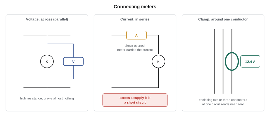
A voltmeter measures the potential difference between two points, so it is connected across them, in parallel with whatever is between them. It has a very high internal resistance, typically ten megohms on a digital meter, so it draws almost no current and does not disturb the circuit. Measuring voltage is the safest and most useful measurement in elevator work, because the leads only touch the circuit at two points and the circuit is not changed.
An ammeter measures the current through a conductor, so the current must pass through it: the circuit is opened and the meter connected in series. Its internal resistance is very low so that it does not drop much voltage. Connecting an ammeter across a supply, in parallel, is a short circuit through the meter. A good meter protects itself with a high-energy fuse, but a meter with the wrong fuse, or one used with its leads in the current jacks while measuring voltage, can explode in the hand. For that reason Northcrest mechanics rarely use the series current function on power circuits. They use a clamp meter.
A clamp meter measures current by sensing the magnetic field around a conductor. The jaws are closed around one conductor, and the meter reads the current without any connection to the circuit. It works on AC and, with a Hall-effect sensor, on DC too. The jaws must enclose only one conductor of the circuit: if they enclose both the outgoing and return conductors, the fields cancel and the meter reads zero. A clamp around all three phase conductors of a motor feed reads near zero for the same reason, unless there is leakage current to ground, which is how leakage clamps find ground faults.
An ohmmeter measures resistance by passing a small current from its own battery through the component and measuring the voltage. It must only be used on a circuit that is locked out and verified dead. Any voltage from the circuit will give a false reading and may damage the meter. Resistance readings are also affected by parallel paths: a coil measured while still connected may read low because another component is in parallel with it. When the reading matters, one end of the component is disconnected.
Meter categories and ratings
Meters, test leads and accessories are rated under the international standard for electrical test equipment by measurement category and voltage. The category reflects how much energy a transient or fault can deliver at that point in the installation. Category IV is the origin of the installation, at the service entrance and utility meter. Category III is the distribution level inside the building: panelboards, feeders, motor starters and fixed equipment such as an elevator controller and its mainline disconnect. Category II covers equipment plugged into receptacles. A meter rated CAT II is not suitable for a controller even if its voltage rating is high enough.
For elevator work, the meter and leads should be rated at least CAT III for the system voltage, and for 480 V equipment Northcrest specifies CAT III 1000 V or CAT IV 600 V. The rating of a measurement set is the lowest rating of any part of it, so a cheap set of leads or an alligator clip with a lower rating downgrades the whole set. Test leads should have shrouded connectors, finger guards and short exposed tips, often four millimeters or less, which reduce the chance of an accidental short between two terminals.
| Category | Where | Elevator example |
|---|---|---|
| CAT IV | Origin of the installation | Service entrance, utility meter, outdoor conductors |
| CAT III | Distribution inside the building | Mainline disconnect, controller power terminals, feeders, the hoist motor |
| CAT II | Plug-connected loads | A receptacle in the machine room, a portable tool |
| CAT I or unrated | Protected electronic circuits | Only where the manufacturer says so |
Ghost voltages and low-impedance mode
A digital voltmeter's high impedance is usually an advantage, but it has a side effect. Conductors run side by side in a conduit, a raceway or a traveling cable are coupled to each other by capacitance. A conductor that has been disconnected at both ends, or whose switch is open, can pick up a voltage from its live neighbors through that coupling. The coupling can supply only a tiny current, but a ten-megohm meter draws almost nothing, so the meter reads a substantial voltage that is not really there. These ghost voltages are common in elevator wiring, which is full of long parallel runs.
The danger is in both directions. A ghost reading can make a dead circuit look live and send a mechanic looking for a fault that does not exist. More rarely, a mechanic who is used to ghost readings may dismiss a real voltage as a ghost. The cure is a meter with a low-impedance voltage mode, often marked LoZ, which puts a load of a few kilohms across the leads. A real voltage source holds up under that load; a capacitively coupled ghost collapses to near zero. The code below models the coupling as a small capacitor between the live conductor and the open one.
# Ghost voltage on an open conductor coupled to a live neighbor (illustrative)
import math
f = 60.0                # Hz
v_live = 120.0           # V on the neighboring conductor
c_coupling = 2.0e-9     # F, roughly 2 nF over a long parallel run
xc = 1 / (2 * math.pi * f * c_coupling)    # coupling reactance, ohms
for name, z_meter in (("high impedance, 10 Mohm", 10e6), ("low impedance mode, 3 kohm", 3e3)):
    # the meter and the coupling form a divider (treat both as magnitudes in quadrature)
    v = v_live * z_meter / math.sqrt(z_meter ** 2 + xc ** 2)
    print(f"{name:<28} reads {v:6.1f} V")
print(f"coupling reactance {xc / 1e6:.2f} Mohm")high impedance, 10 Mohm reads 119.0 V low impedance mode, 3 kohm reads 0.3 V coupling reactance 1.33 Mohm
The high-impedance meter shows most of the neighboring voltage on a conductor that is not connected to anything. The low-impedance mode reads less than a volt. When Tamsin finds an unexpected voltage on a conductor that should be dead, Ray has her switch to LoZ and measure again before drawing any conclusion. Low-impedance mode should not be used on sensitive electronic circuits, because its load can disturb them, and it should not be left connected to a live circuit for long, because it draws real current.
RMS and drive outputs
Alternating voltages and currents are stated as RMS values, the root-mean-square, which is the value that would produce the same heating as a DC value of the same size. Lesson 5 explains where the numbers come from. Inexpensive meters do not measure RMS directly. They measure the average of the rectified waveform and multiply by a factor that is correct only for a pure sine wave. On a clean sine wave they are accurate. On the distorted current drawn by a rectifier, or the pulse-width-modulated output of a variable-frequency drive, they can be wrong by a large margin.
A true-RMS meter calculates the RMS value from the waveform itself and stays accurate on distorted waveforms. Even then, the output of a drive is a series of high-frequency pulses, and many meters read it erratically. Better meters have a low-pass filter setting, sometimes marked VFD, that removes the switching frequency so that the meter shows the fundamental voltage the motor actually responds to. Priya's rule is that motor voltages on the output side of a drive are read with the filter on, or not trusted.
Insulation resistance testing
An insulation resistance tester, often called a megohmmeter, applies a high DC voltage, typically 500 or 1,000 V, between a conductor and ground or between two conductors, and measures the very small current that leaks through the insulation. Good insulation reads in the hundreds or thousands of megohms. Damp, contaminated or damaged insulation reads lower. The test finds faults that a normal ohmmeter, which tests at a few volts, cannot see, such as a hoist motor winding that has absorbed moisture or a traveling cable conductor with a nicked jacket.
The test voltage is high enough to destroy electronic equipment. Before testing a motor or a cable, the conductors are disconnected from the drive, the controller boards and any surge suppressors, and the circuit is locked out and verified dead. After the test, the conductor is discharged to ground, because the cable and winding capacitance stores a charge from the tester. Readings are recorded with the temperature, because insulation resistance falls steeply as temperature rises. A common rule of thumb is that it halves for every 18 degrees Fahrenheit of temperature rise, so readings are corrected to a reference temperature before they are compared with earlier ones.
# Insulation resistance of the Tillicum car 1 hoist motor over three years
# readings at 1,000 V, one minute, corrected to 104 F with a halving per 18 F rule
readings = [  # (year, measured Mohm, winding temperature F)
    (2024, 850.0, 71.6),
    (2025, 610.0, 82.4),
    (2026, 140.0, 87.8),
]
for year, mohm, t in readings:
    corrected = mohm * 0.5 ** ((104 - t) / 18)
    print(f"{year}: measured {mohm:6.0f} Mohm at {t:5.1f} F -> {corrected:6.0f} Mohm at 104 F")
first = readings[0][1] * 0.5 ** ((104 - readings[0][2]) / 18)
last = readings[-1][1] * 0.5 ** ((104 - readings[-1][2]) / 18)
print(f"change since first test: {100 * (last / first - 1):.0f} %")2024: measured 850 Mohm at 71.6 F -> 244 Mohm at 104 F 2025: measured 610 Mohm at 82.4 F -> 266 Mohm at 104 F 2026: measured 140 Mohm at 87.8 F -> 75 Mohm at 104 F change since first test: -69 %
The corrected figures make the trend clear. The winding is still well above any minimum, but its resistance has fallen sharply in a year, and the trend matters more than the absolute value. Ray puts a note on the Tillicum file to inspect the motor for moisture and contamination, and to retest after cleaning and drying.
Continuity, diode and other tests
Most meters have a continuity function that beeps when the resistance is below a few tens of ohms. It is quick for checking a fuse, a wire or a closed contact on a dead circuit. The diode test applies a small current in one direction and reports the forward voltage of a diode, about 0.5 to 0.7 V for a silicon diode, and an open reading in the reverse direction. It is used on the rectifiers that feed brake coils and on the suppression diodes across DC relay coils. Some technicians also carry a small oscilloscope or a meter with a recording function, which can capture an intermittent dropout that is too quick to see on a display.
Worked problem
Is the door operator feed really dead?
At the Marlowe Apartments, Tamsin is checking the car door operator. The operator's supply breaker is off and locked, but her meter reads 46 V AC between the operator terminals and ground. Ray asks her what she should conclude.
Show solution
- The circuit was verified dead at the breaker with a live-dead-live test, so the reading could be a ghost voltage coupled from live conductors in the traveling cable.
- She switches the meter to its low-impedance mode and measures again: 0.3 V.
- A real source would hold its voltage under the low-impedance load; a ghost collapses.
- She also confirms the breaker label against the panel schedule, to be certain the right circuit is off.
Answer: The 46 V was capacitively coupled. The circuit is dead, but the conclusion is drawn only after the low-impedance test and a check that the right breaker is locked.
Common mistakes
MistakeMeasuring voltage with the leads still in the current jacks.
InsteadCheck the lead positions before every voltage measurement; a meter in current mode across a supply is a short circuit.
MistakeUsing a CAT II meter in a controller.
InsteadUse meters and leads rated at least CAT III for the system voltage.
MistakeClamping around both conductors of a circuit.
InsteadEnclose one conductor; outgoing and return currents cancel.
MistakeMeasuring resistance on a live circuit.
InsteadLock out and verify dead first; disconnect one end if parallel paths could affect the reading.
MistakeMegohm-testing a motor with the drive still connected.
InsteadDisconnect electronics before applying the test voltage, and discharge the circuit afterwards.
Summary and key terms
- Voltmeters connect in parallel and draw almost no current; ammeters connect in series and have very low resistance.
- Clamp meters measure current without breaking the circuit, around one conductor only.
- Meters and leads must be rated CAT III or higher for elevator controllers at the system voltage.
- High-impedance meters can show ghost voltages on dead conductors; low-impedance mode distinguishes them.
- True-RMS meters, with a filter on drive outputs, are needed for distorted waveforms.
- Insulation resistance tests find deteriorating insulation; readings are corrected for temperature and trended.
- Clamp meter
- A meter that measures current by sensing the magnetic field around a conductor.
- Measurement category
- A rating that reflects the transient energy available at a point in the installation.
- Ghost voltage
- A voltage read on a disconnected conductor through capacitive coupling, which collapses under load.
- Low-impedance mode
- A meter setting that loads the circuit so that ghost voltages collapse.
- True RMS
- A measurement of the effective value calculated from the actual waveform.
- Insulation resistance tester
- An instrument that applies a high DC voltage to measure the leakage resistance of insulation.
Practice problems
Work each problem on paper first, then reveal the answer to check.
Why is an ammeter connected in series and a voltmeter in parallel?
Show answer
Current must flow through the ammeter to be measured; voltage is the difference between two points, so the voltmeter goes across them.
A clamp meter around all three conductors of a motor feed reads 0.4 A. What does that indicate?
Show answer
The phase currents should cancel; 0.4 A is leakage current returning by another path, a sign of a ground fault.
An insulation reading of 400 Mohm was taken at 68 °F. Corrected to 104 °F with the halving rule, what is it?
Show answer
400 × 0.5² = 100 Mohm.
Your meter reads 60 V on a conductor you have locked out. What do you do?
Show answer
Measure again in low-impedance mode; if the voltage holds, treat it as a real source and find it before going further.
Lesson quiz · 5 questions
Score 60% or more to complete this lesson.
Create a free account to save your progress, take quizzes and earn a certificate.