
ELV-210 · Lesson 12 of 12 · 21 min
Capstone: electrical troubleshooting on a traction elevator
The last session of the electrical block is not held in the training room. Priya arranges for the class to follow two real fault calls from Tamsin's field log, worked through on the drawings with the readings she and Ray took. The first is on Tillicum car 1, the Ward-Leonard relay car of Lesson 8, which had been stopping between floors without warning. The second is on Quayside car 2, a gearless machine with a regenerative drive, which refused to start one morning with a drive fault. Between them they use almost every lesson in the course: safety and lockout, Ohm's law and voltage drop, series strings, meters, three-phase supplies, relays and contactors, DC and AC motors, drives and drawings. The point of the capstone is the method, which is the same on any elevator: make it safe, gather information, form a hypothesis from the drawings, test it with measurements, repair, and prove the repair.
Call one: Tillicum car 1 stops between floors
The building manager's complaint was that car 1 had stopped between floors three times in two weeks, always in the afternoon, and each time had run normally after the mechanic on call reset it. The service log showed the three callbacks, each closed with the same note: car found stopped, safety circuit open, reset, ran on test, no fault found. Ray's opinion of a log like that is that the fault has been found three times and fixed none of them.
Making it safe and gathering information
Before opening anything, Ray and Tamsin took the car out of service at the lobby with a barricade and a sign, told the building manager, and planned the work. They would need the car live, because an intermittent fault in a safety circuit can only be found while the circuit is energized and the car is moving. That made the job diagnostic testing of the kind Lesson 1 described: arc-rated clothing and face protection on whenever the controller was open, rated gloves for any reading on the 480 V side, Ray as the qualified mechanic in charge of the live work, and Tamsin taking readings only under his direct supervision. No jumpers would be placed.
The information came from three places. The drawings showed the safety string on line 3 of the schematic: wire 10 from the control transformer secondary fuse, through the machine room stop switch, governor switch, final limits, pit stop switch, buffer switches, car top stop switch and car safety switch, to wire 19 and the SAF relay coil. The log gave the pattern: afternoons, on up runs, mid-hoistway. And the car itself, which Ray rode on inspection with Tamsin watching the SAF relay in the controller over the radio, ran normally for twenty minutes.
First measurements
Ray started with the supply, because a low or unbalanced supply makes every relay marginal. The three line-to-line voltages at the mainline disconnect, the control transformer secondary voltage at idle and while the motor-generator set started, and the motor-generator set's AC motor current were all recorded.
# Tillicum car 1: supply and control voltage checks
import math
lines = {"L1-L2": 477, "L2-L3": 481, "L3-L1": 476}
avg = sum(lines.values()) / 3
unb = 100 * max(abs(v - avg) for v in lines.values()) / avg
print(f"supply average {avg:.0f} V, unbalance {unb:.1f} %")
ratio = 4.0
idle, mg_start = 118.5, 111.0
print(f"control secondary expected {avg / ratio:.1f} V idle, measured {idle} V")
print(f"dip during M-G start {idle - mg_start:.1f} V ({100 * (idle - mg_start) / idle:.0f} %), "
      f"still above relay pickup of {0.8 * 120:.0f} V")
mg_amps = [26.9, 27.5, 27.2]
print("M-G motor currents", mg_amps, f"spread {100 * (max(mg_amps) - min(mg_amps)) / (sum(mg_amps) / 3):.0f} %")supply average 478 V, unbalance 0.6 % control secondary expected 119.5 V idle, measured 118.5 V dip during M-G start 7.5 V (6 %), still above relay pickup of 96 V M-G motor currents [26.9, 27.5, 27.2] spread 2 %
The supply was well balanced, the control transformer secondary was where its ratio said it should be, and it dipped only a few volts when the motor-generator set started. The motor-generator set was drawing balanced currents. Nothing on the supply side explained an intermittent safety trip, so the next place to look was the string itself.
Measuring along the string
With the car idle at the lobby, Tamsin measured from each terminal of the safety string to the common rail, working down the drawing from wire 10. Every terminal read between 118 and 119 V, and the SAF coil terminal, wire 19, read 117.9 V. The string was complete and all its contacts looked good with the car stationary. Then she repeated the readings across each contact, rather than to common, while Ray ran the car up and down on inspection from the car top. On a healthy string, each closed contact should read almost nothing.
# Readings across each safety string contact, car running on inspection
coil_r = 2400.0
supply = 118.5
readings = {   # volts measured across each closed contact while running (max seen)
    "machine room stop": 0.0, "governor switch": 0.1, "final limit top": 0.0,
    "final limit bottom": 0.0, "pit stop": 0.0, "buffer switch": 0.1,
    "car top stop": 9.0, "car safety switch": 0.1,
}
total_drop = sum(readings.values())
coil_v = supply - total_drop
i = coil_v / coil_r
for name, v in readings.items():
    r = v / i if i else 0
    flag = "  <-- investigate" if v > 1.0 else ""
    print(f"{name:<20} {v:5.1f} V  about {r:6.1f} ohm{flag}")
print(f"coil voltage while running {coil_v:.1f} V; relay drops out below about 40 V")machine room stop 0.0 V about 0.0 ohm governor switch 0.1 V about 2.2 ohm final limit top 0.0 V about 0.0 ohm final limit bottom 0.0 V about 0.0 ohm pit stop 0.0 V about 0.0 ohm buffer switch 0.1 V about 2.2 ohm car top stop 9.0 V about 197.8 ohm <-- investigate car safety switch 0.1 V about 2.2 ohm coil voltage while running 109.2 V; relay drops out below about 40 V
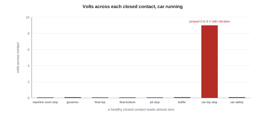
The car top stop switch read up to 9 V across its closed contacts while the car moved, jumping between zero and nine with the vibration. Nine volts across the contact with only about 45 mA flowing means its contacts were intermittently reaching about two hundred ohms. The coil still had over a hundred volts, so the relay held during the test, but a contact that can reach two hundred ohms on a vibration can also open momentarily, and a brief open is all it takes for SAF to drop and the car to stop. The afternoon pattern fitted too: the car top was warm on a sunny afternoon under the machine room, and the switch was an old one whose contacts were pitted.
Ray locked out the controller and the car lighting circuit, verified both dead with the live-dead-live test, and replaced the car top stop switch with a new one of the type the drawing specified. He checked the wiring at the car top junction box, where wires 16 and 17 to the switch were tight, and recorded the change on the drawing and in the log.
Proving the repair
After restoring power, Tamsin repeated the readings across every contact with the car running, and the car top stop switch now read zero. Ray then ran the car on normal operation for an hour while the building was busy, with Tamsin watching the SAF relay. He also tested the switch itself: opening it with the car on inspection must stop the car, and the car must not restart when it is closed again until a new run command is given. Only then did he return the car to service. The log entry this time read: intermittent safety circuit open, 9 V measured across car top stop switch contacts while running, switch replaced, readings after repair 0 V, car run one hour on normal operation, switch function tested.
Call two: Quayside car 2 will not start
The second call came early on a weekday morning. Quayside car 2 had shut down overnight, and the controller display showed a drive fault for overcurrent at start, and a brake monitoring fault. The car would attempt a run, the drive would hold torque for a moment, then trip, and the car would not move. Priya was on the phone to the site, and Tamsin was with Ray in the control space at the top landing.
The fault log in the drive gave the clues. At the moment of each trip, the drive had been holding the car at zero speed with high current, the brake had been commanded to lift, and the brake lift monitoring switches had reported one brake lifted and the other not. The Quayside machines have a dual-circuit brake: two independent brake units, each able to hold the car on its own, each with its own coil and its own lift monitoring switch. The drive was trying to hold the car against a brake that had not released, and its current rose until it tripped.
Ray's hypothesis came from Lessons 2 and 7. If one brake was not lifting, either its coil was not getting the right voltage, its coil was open, or the brake was mechanically stuck. He measured the brake controller outputs to each coil during a start attempt: brake A received the 190 V lifting voltage and then dropped to 95 V holding, exactly as specified. Brake B received the same lifting voltage at the brake controller terminals, but the clamp meter on the brake B lead read no current at all.
# Quayside car 2 dual brake: expected and measured coil currents
spec = {"R_cold": 76.0, "lift_v": 190.0, "hold_v": 95.0}   # coil resistance at 68 F
temp = 64.4        # control space temperature in the morning, F
alpha = 0.00218
r = spec["R_cold"] * (1 + alpha * (temp - 68))
exp_lift, exp_hold = spec["lift_v"] / r, spec["hold_v"] / r
measured = {"brake A": (2.49, 1.25), "brake B": (0.00, 0.00)}
print(f"expected: lift {exp_lift:.2f} A, hold {exp_hold:.2f} A (coil {r:.1f} ohm at {temp} F)")
for name, (lift, hold) in measured.items():
    state = "ok" if abs(lift - exp_lift) / exp_lift < 0.15 else "open circuit" if lift == 0 else "check"
print(f"{name}: lift {lift:.2f} A, hold {hold:.2f} A -> {state}")expected: lift 2.52 A, hold 1.26 A (coil 75.4 ohm at 64.4 F) brake A: lift 2.49 A, hold 1.25 A -> ok brake B: lift 0.00 A, hold 0.00 A -> open circuit
With voltage at the brake controller but no current, the open had to be between the brake controller terminals and the coil. With the controller and drive locked out, the DC bus measured below 50 V, and the car secured by the other brake and the drive's motor shorting contactor as the manufacturer's procedure required, Tamsin measured the resistance of brake B's coil at the machine connector: 75.4 ohms, correct for its temperature. The coil was good. She then measured from the brake controller terminal to the machine connector, wire by wire: one conductor read open. The connector on the machine end had a crimp that had pulled out of its pin, probably disturbed when an encoder cable had been rerouted the previous week.
Ray replaced the pin, checked the other pins in the connector by pulling on each wire gently, and dressed the cable so that it could not be strained again. After restoring power, the start attempt showed both brakes lifting with the right currents, both monitoring switches changing state, and a normal start with low current at zero speed. The drive's fault log was saved and attached to the service record before being cleared, and a note went to the installation crew about the cable routing.
What the two calls have in common
Neither fault was found by replacing parts. Both were found by reading the drawings, predicting what a meter should read at each point, and measuring until a reading disagreed with the prediction. In the first call, Ohm's law and the series string told Tamsin that a closed contact should read almost nothing, and a reading of nine volts was the disagreement. In the second, the brake coil's resistance and the brake controller's output told her what current to expect, and a reading of zero was the disagreement. In both, the readings that agreed with the prediction were just as useful, because each one eliminated part of the circuit.
Both calls also show where safety fits into troubleshooting. The diagnostic work was done live, with the protection the hazard required. The repairs were done locked out and verified dead, with stored energy dealt with, the drive bus on Quayside, the car itself on both, before anyone touched a conductor. And the repairs were proved by test before the cars went back into service.
Worked problem
Writing up the Quayside call
Priya asks each member of the class to write the service report for the Quayside call as if they were Tamsin. What does a good report contain?
Show solution
- The symptom and the fault codes, with the drive fault log saved and attached.
- The hypothesis and the readings that tested it: brake A and B voltages at the brake controller, brake B current zero, coil resistance 75.4 ohms at the connector, one conductor open.
- The safety steps: lockout points, DC bus verified below 50 V, car secured by the other brake as the manufacturer's procedure requires.
- The repair, the checks on the rest of the connector, the cable dressing, and the test results after repair: both brake currents, both monitoring switches and a normal start.
- The probable cause and the follow-up: the cable disturbed during last week's encoder cable rerouting, and the note sent to the installation crew.
Answer: A good report lets the next mechanic understand the fault, the evidence and the repair without having been there.
Common mistakes
MistakeClosing a callback as no fault found after a reset.
InsteadAn intermittent trip is a fault; measure while running until it is found.
MistakeReplacing the brake coil because the brake would not lift.
InsteadMeasure voltage and current first; a good coil with no current points to the wiring.
MistakeMeasuring the string only with the car stationary.
InsteadVibration-sensitive faults show up only with the car moving.
MistakeClearing the drive fault log before saving it.
InsteadThe snapshot at the moment of the fault is evidence.
MistakeReturning the car to service straight after the repair.
InsteadProve the repair: repeat the readings, test the device and run the car.
Summary and key terms
- Troubleshooting follows a fixed method: make safe, gather information, hypothesize from the drawings, measure, repair and prove.
- Supply and control voltages are checked first, because they make every relay and drive marginal.
- Readings across closed contacts while running find resistive contacts that cause intermittent trips.
- Comparing measured currents with values predicted from coil resistance and voltage locates open circuits.
- Diagnosis is done live with the right protection; repairs are done locked out with stored energy controlled.
- Every repair is proved by test and recorded so the next mechanic can follow it.
- Callback
- A service call in which the customer reports a fault on equipment already in service.
- Intermittent fault
- A fault that comes and goes, often with vibration, temperature or load.
- Hypothesis
- A proposed cause, based on the drawings and the symptoms, that measurements will test.
- Dual-circuit brake
- A brake with two independent units, each able to hold the car, each monitored.
- Brake lift monitoring
- Switches that report to the controller whether each brake has lifted.
- Fault log
- The record stored by a drive or controller of faults and the conditions when they occurred.
Practice problems
Work each problem on paper first, then reveal the answer to check.
A closed safety contact reads 6 V while 50 mA flows through the string. What resistance is it showing?
Show answer
6 / 0.05 = 120 ohms.
Why did Ray check the supply before the safety string?
Show answer
A low or unbalanced supply or a sagging control transformer makes relays marginal and could explain intermittent trips.
A brake coil rated 190 V lift measures 75 ohms. What lifting current should it draw?
Show answer
190 / 75 = about 2.5 A.
List the steps that make the Quayside brake wiring safe to work on.
Show answer
Lock out the controller and drive, verify dead with live-dead-live, verify the DC bus below 50 V, and secure the car as the manufacturer's procedure requires.
Lesson quiz · 5 questions
Score 60% or more to complete this lesson.
Create a free account to save your progress, take quizzes and earn a certificate.