
ELEC-430 · Lesson 11 of 12 · 25 min
Theory review: machines, electronics, communications and safety
Theory questions test whether you understand how electrical equipment works, not just how to install it. They cover magnetism and induction, generators and transformers, motors and their starting and control, electronics and power conversion, signaling and communication systems, and the safety knowledge that underpins all work. Many theory questions are quick for candidates who have reviewed the principles and slow or impossible for those who have not, so a structured theory review gives a good return on study time. This lesson summarizes the theory most commonly examined, with short examples and checks.
Magnetism and induction
Current in a conductor produces a magnetic field around it, whose direction follows the right-hand rule. Coiling the conductor concentrates the field, and an iron core multiplies it many times, the principle of electromagnets, relays, contactors and solenoids. Faraday's law states that a changing magnetic flux through a coil induces a voltage proportional to the rate of change and the number of turns; Lenz's law states that the induced current opposes the change that caused it. These two laws explain generators, transformers, induction motors, inductive kickback when relay coils are switched off, and eddy current heating in metal enclosures when a single conductor passes through a steel opening alone, which is why all conductors of a circuit must pass through the same opening in ferrous metal.
Generators and alternators
A generator converts mechanical energy into electrical energy by rotating conductors through a magnetic field, or a field past conductors. In an AC alternator, the frequency is fixed by speed and the number of poles: \(f = PN/120\), where \(P\) is the number of poles and \(N\) the speed in r/min. A two-pole machine must turn at 3,600 r/min for 60 Hz, a four-pole machine at 1,800 r/min. Output voltage is controlled by the field current through the voltage regulator. Generators operating in parallel must match voltage, frequency, phase sequence and phase angle before the breaker closes, the process called synchronizing. Standby generators supply buildings through transfer switches that prevent backfeed into the utility.
Transformers
Transformers rely on mutual induction between windings on a common core. Their losses include copper losses in the windings, which vary with the square of the load, and core losses from hysteresis and eddy currents, which are roughly constant whenever the transformer is energized. Common three-phase connections include delta–wye, which provides a neutral on the secondary and a 30° phase shift, and wye–wye, used with care because of third-harmonic and neutral issues. Autotransformers share a winding between primary and secondary, making them smaller but without isolation. Instrument transformers, current transformers and potential transformers, step currents and voltages down to levels suitable for meters and relays; a CT secondary must never be opened while the primary carries current, because it develops a dangerous voltage.
Three-phase induction motors
Three-phase currents in the stator windings of an induction motor produce a rotating magnetic field turning at synchronous speed, \(N_s = 120f/P\). The field induces currents in the rotor bars, which produce torque. The rotor must turn slightly slower than the field for induction to occur; the difference, expressed as a fraction of synchronous speed, is slip, typically 2 to 5 % at full load. Reversing any two supply lines reverses the rotation. Starting current is typically six to eight times full-load current, which is why reduced-voltage starting methods are used for large motors: autotransformer starters, wye–delta starters, which reduce starting current and torque to one third, part-winding starters, solid-state soft starters and variable frequency drives.
Worked problem
Speed and slip
A four-pole, 60 Hz induction motor runs at 1,750 r/min at full load. What are the synchronous speed and slip?
Show solution
- Synchronous speed: \(N_s = 120 \times 60 / 4 = 1{,}800\) r/min.
- Slip speed: 1,800 − 1,750 = 50 r/min.
- Slip: 50 / 1,800 = 2.8 %.
Answer: Synchronous speed 1,800 r/min; slip about 2.8 %.
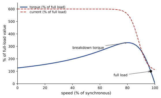
Single-phase and DC motors
Single-phase motors need a starting mechanism because a single-phase winding produces a pulsating, not rotating, field. Split-phase motors use a start winding with a centrifugal switch; capacitor-start motors add a capacitor for higher starting torque; permanent split capacitor motors keep a run capacitor in circuit and are common in fans and compressors; shaded-pole motors are small, cheap and inefficient. Electronically commutated (EC) motors, increasingly used in fans and pumps, combine a permanent magnet motor with built-in electronics. DC motors are classified by field connection: series motors have very high starting torque and must never run unloaded, because their speed rises dangerously; shunt motors run at nearly constant speed; compound motors combine both characteristics. DC motor speed is controlled by armature voltage and field current.
Motor control
Control circuits use relays, contactors, timers, pushbuttons, limit switches, pressure switches and other devices to start, stop and sequence equipment. Ladder diagrams show control logic with power rails on each side and rungs for each circuit, with contacts drawn in their normal (de-energized) state. Key concepts include holding (seal-in) contacts, interlocks that prevent conflicting operations such as forward and reverse at once, jogging, timed sequences using on-delay and off-delay timers, and safety circuits that stop equipment when a guard opens. Programmable logic controllers (PLCs) replace hard-wired logic with programs, reading inputs and setting outputs in a repeated scan; exam questions may ask about input and output wiring, sinking and sourcing, and basic ladder logic.
Electronics and power conversion
Diodes allow current in one direction only. A single diode gives half-wave rectification; four diodes in a bridge give full-wave rectification, producing pulsating DC that capacitors smooth. Silicon-controlled rectifiers (SCRs) conduct when triggered and are used in controlled rectifiers and older drives; triacs control AC in dimmers and heaters. Transistors, including the insulated-gate bipolar transistors (IGBTs) in modern drives and inverters, switch rapidly to synthesize variable-frequency output by pulse-width modulation. These switching devices draw non-sinusoidal currents, creating harmonics that heat neutrals and transformers and can disturb other equipment, which links electronics theory to the code's rules on neutrals and transformer sizing. Uninterruptible power supplies (UPS), battery chargers, LED drivers and solar inverters all rely on these devices.
| Device | Function | Typical use |
|---|---|---|
| Diode | One-way conduction | Rectifiers, flyback protection across relay coils |
| SCR | Triggered one-way conduction | Controlled rectifiers, soft starters |
| Triac | Triggered two-way conduction | Dimmers, heater controls |
| IGBT | Fast switching of high power | VFDs, inverters, UPS |
| Capacitor | Stores charge, smooths voltage | Filters, power factor correction, motor starting |
| Thermistor or RTD | Resistance changes with temperature | Temperature sensing and motor protection |
Signaling and communication systems
Electricians install many low-energy systems: fire alarm initiating devices and notification appliances, nurse call, security and access control, intercoms, data cabling and fiber optics, and building automation. Fire alarm initiating circuits connect smoke detectors, heat detectors and manual pull stations to the control unit, and supervision with end-of-line resistors or addressable loops detects open circuits. Notification appliance circuits supply horns, strobes and speakers. Structured cabling uses twisted-pair cable, such as Category 6 for data networks, with limits on segment length (90 m permanent link plus patch cords, 100 m channel), bend radius and untwisting at terminations, and must be kept separate from power wiring or segregated by barriers. Fiber optic cable carries light, is immune to electrical interference, and is classified as single-mode for long distances and multimode for shorter runs; it must not be bent tighter than its minimum radius and connections must be kept clean.
US installations follow NEC Article 725 (Class 2 and 3 circuits, reorganized into Articles 722 to 726 in recent editions), Article 760 (fire alarm), Article 770 (optical fiber, merged into Chapter 7 limited-energy articles in 2026) and Chapter 8 (communications), together with NFPA 72 and the TIA cabling standards.
Safety knowledge
Safety questions appear in every part of the exam. Key topics include the effects of current on the body, from perception around 1 mA, through let-go thresholds around 10 mA, to ventricular fibrillation from about 50 to 100 mA across the chest for a second; arc flash and arc blast hazards, incident energy and arc-rated PPE; establishing an electrically safe work condition by isolating, locking out, tagging, verifying absence of voltage with a tested meter, and grounding where needed; approach boundaries; ladder, fall protection and confined space safety; and handling of hazardous materials, such as battery electrolytes and sealing compounds.
In the United States, NFPA 70E, Standard for Electrical Safety in the Workplace, sets out safe work practices, arc flash risk assessment and PPE, and OSHA regulations, including 29 CFR 1910 Subpart S and 1926 Subpart K, make many of these practices legally required. The OSHA Hazard Communication Standard governs labeling and safety data sheets.
Common occupational skills
Exams also test general trade knowledge: reading drawings and specifications, including electrical symbols, single-line diagrams, schedules and riser diagrams; using and caring for tools and test instruments, including choosing a meter with the right measurement category; planning and organizing work; communication and mentoring; and documentation such as permits and inspection requests. These questions often seem easy but are worth the same as hard calculations, so review symbols and drawing conventions to secure the marks.
Lighting and lighting controls
Lighting theory appears on many exams. Light output is measured in lumens, illuminance in lux (lumens per square meter) or footcandles (lumens per square foot), and efficacy in lumens per watt. LED luminaires have largely replaced fluorescent and high-intensity discharge lamps, offering efficacies above 100 lumens per watt, long life and easy dimming, but they rely on drivers that convert AC to regulated DC and can introduce harmonics and compatibility issues with dimmers. Lighting controls, required by energy codes in many buildings, include occupancy and vacancy sensors, daylight harvesting with photosensors, time schedules and networked control systems, and they must be commissioned to work as intended.
Batteries and DC systems
Batteries store energy for emergency lighting, uninterruptible power supplies, solar systems, electric vehicles and substations. Lead-acid batteries need ventilation because they release hydrogen when charging, and electrolyte presents a chemical hazard; lithium-ion batteries have higher energy density but can suffer thermal runaway, so they need battery management systems and appropriate fire protection. Battery capacity is rated in ampere-hours, and connecting cells in series raises voltage while connecting them in parallel raises capacity. DC circuits behave differently from AC when interrupted, because DC arcs do not extinguish at a current zero, so switches and breakers must be rated for DC at the system voltage.
Grounding theory and touch voltage
A final theory topic links back to grounding. When a fault occurs, the voltage between a faulted enclosure and the earth, the touch voltage, depends on the impedance of the fault path and the current flowing. A low-impedance bonding path keeps touch voltage low and causes the protective device to operate quickly, limiting the time a person is exposed. This explains the emphasis on bonding conductor sizing and continuity in Lesson 6, and the use of equipotential bonding in pools and farm buildings in Lesson 9.
Protection relays and metering
Larger installations use protective relays fed by current and voltage transformers to detect faults and abnormal conditions and trip circuit breakers. Common functions include overcurrent, ground fault, undervoltage, phase loss and reverse power. Revenue and power quality meters use the same instrument transformers to measure energy, demand, power factor and harmonics. Exam questions may ask about the purpose of a relay function, the connection of current transformers, or the safety precautions when working on instrument transformer circuits.
Reading control diagrams
Exams often include a control diagram and ask what happens when a button is pressed or a contact opens. Trace the circuit rung by rung, noting which contacts are normally open or closed and which coils they belong to. Remember that a contact changes state only when its coil is energized, and that timers delay their contact changes according to their type. Practicing with several diagrams makes these questions quick.
Common mistakes
MistakeConfusing synchronous speed with rated speed.
InsteadRated speed is lower by the slip.
MistakeOpening a CT secondary under load.
InsteadShort the CT secondary before disconnecting meters or relays.
MistakeRunning a series DC motor without load.
InsteadKeep series motors coupled to their load.
MistakeReading ladder contacts as shown in their operated state.
InsteadDiagrams show contacts de-energized.
MistakeRunning data cable alongside power wiring.
InsteadSeparate or segregate communication cables.
Summary and key terms
- Faraday's and Lenz's laws explain generators, transformers and motors.
- Alternator frequency f = PN/120; parallel generators must be synchronized.
- Transformer losses are copper (load) and core (constant).
- Induction motors run at slip below synchronous speed, 120f/P.
- Reduced-voltage starting limits large motors' starting current.
- Rectifiers, SCRs, triacs and IGBTs underpin drives and power supplies and create harmonics.
- Communication systems and safety practices are examinable alongside power theory.
- Faraday's law
- Changing flux induces voltage.
- Lenz's law
- Induced current opposes its cause.
- Synchronous speed
- Speed of the rotating field, 120f/P.
- Slip
- Difference between synchronous and rotor speed.
- Wye–delta starter
- Starter reducing starting current to one third.
- Current transformer
- Transformer stepping current down for metering.
- Ladder diagram
- Control drawing with rungs between rails.
- IGBT
- High-power fast switching transistor.
- Rectifier
- Converts AC to DC.
- End-of-line resistor
- Device enabling circuit supervision.
Practice problems
Work each problem on paper first, then reveal the answer to check.
Speed of a six-pole, 60 Hz alternator?
Show answer
1,200 r/min.
Synchronous speed of a two-pole, 60 Hz motor?
Show answer
3,600 r/min.
Slip of a 1,800 r/min field with rotor at 1,746 r/min?
Show answer
3 %.
How do you reverse a three-phase motor?
Show answer
Swap any two supply lines.
What fraction of starting current does wye–delta give?
Show answer
One third.
Which transformer losses vary with load?
Show answer
Copper (winding) losses.
Why must a CT secondary not be opened?
Show answer
It develops a dangerous high voltage.
Which DC motor must never run unloaded?
Show answer
The series motor.
How many diodes in a full-wave bridge?
Show answer
Four.
Maximum Category 6 channel length?
Show answer
100 m.
Lesson quiz · 5 questions
Score 60% or more to complete this lesson.
Create a free account to save your progress, take quizzes and earn a certificate.