
ELE-380 · Lesson 9 of 12 · 34 min
Fault analysis
A fault is an abnormal connection between phases or between a phase and ground: lightning flashing over an insulator, a tree falling on a line, a cable dug up by an excavator, insulation failing inside a transformer. Fault currents can reach tens of times normal load current, and they must be interrupted within a fraction of a second, before they destroy equipment, start fires or destabilize the system. Fault analysis calculates these currents and the voltages during a fault. Its results set the ratings of circuit breakers, switchgear and bus bracing, the settings of protective relays, the grounding design, and the arc-flash hazard at every piece of equipment, the same studies introduced for data centers in DCE-310. This lesson covers the nature of fault currents, symmetrical three-phase faults by Thévenin and bus impedance methods, symmetrical components and unbalanced faults, the effect of system grounding, and equipment ratings.
Types of faults
Faults are classified by the conductors involved:
- Single line-to-ground (SLG): one phase to ground. By far the most common on overhead lines, about 70 to 80% of faults.
- Line-to-line (LL): two phases touching, about 10 to 15%.
- Double line-to-ground (DLG): two phases and ground, about 5 to 10%.
- Three-phase (balanced), with or without ground: the least common, about 2 to 5%, but usually the most severe, and the one that sets most equipment ratings.
Faults may be bolted (zero impedance) or through an arc or ground resistance. Most overhead line faults are temporary: once the breaker opens and the arc is extinguished, the insulation recovers, which is why lines are automatically reclosed after a short delay. Faults in cables and equipment are usually permanent.
The fault current waveform
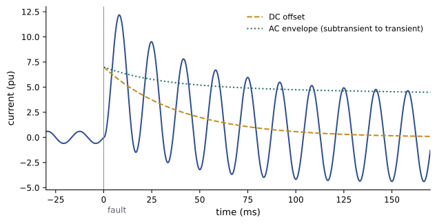
When a fault occurs in an inductive circuit, the current cannot change instantly. For a simple RL circuit energized by a sine wave, the current after the fault consists of a steady-state AC component plus a decaying DC offset that depends on the point on the voltage wave at which the fault occurs. The DC component decays with time constant \(L/R = X/(\omega R)\); with an \(X/R\) ratio of 15 at 60 Hz the time constant is 40 ms, so the offset lasts several cycles. In the worst case, the first peak of current approaches twice the peak of the symmetrical AC component.
Near generators, the AC component itself also decays, because the generator's internal flux changes after a sudden short circuit. This is modeled by three reactances: the subtransient reactance \(X_d''\), which applies for the first few cycles; the transient reactance \(X_d'\), over the next second or so; and the synchronous reactance \(X_d\) in steady state. Fault studies use \(X_d''\) for breaker duty and instantaneous relay settings, and transient values for time-delayed protection.
Symmetrical three-phase faults
A balanced three-phase fault keeps the system balanced, so it can be analyzed per phase with the positive-sequence network in per unit. By Thévenin's theorem, the fault current at a bus equals the prefault voltage divided by the Thévenin impedance seen at that bus, with all sources replaced by their internal impedances:
The short-circuit MVA (fault level) at a bus is a common shorthand for the strength of the system there: a 230 kV bus with a fault level of 10,000 MVA has a Thévenin impedance of 0.01 pu on 100 MVA. Load currents are usually neglected, and prefault voltages are taken as 1.0 pu; loads and line charging have little effect on fault currents, which are dominated by the sources and series impedances.
Worked problem
Fault current from a utility source and a transformer
A 13.8 kV bus has a fault level of 500 MVA. A 10 MVA, 13.8/4.16 kV transformer with 6% impedance feeds a 4.16 kV switchboard. Find the three-phase fault current at the switchboard.
Show solution
- Use a 10 MVA base. Source: \(Z_s = 10/500 = 0.02\) pu. Transformer: 0.06 pu.
- Total: \(0.08\) pu; \(I_f = 1/0.08 = 12.5\) pu.
- Base current at 4.16 kV: \(10 \times 10^6/(\sqrt3 \times 4160) = 1388\) A; \(I_f = 12.5 \times 1388 = 17.3\) kA.
Answer: About 17.3 kA, or a fault level of 125 MVA at the switchboard. Ignoring the source impedance would give 23.1 kA, so an infinite-bus assumption overestimates by a third here.
The bus impedance matrix
For a network with many buses, the Thévenin impedances at all buses are the diagonal elements of the bus impedance matrix \(Z_{\mathrm{bus}} = Y_{\mathrm{bus}}^{-1}\), where \(Y_{\mathrm{bus}}\) is built as in Lesson 6 but with each generator represented by its subtransient reactance to ground. A bolted fault at bus \(k\) gives
so a single matrix gives the fault current at every bus and the voltage at every bus during each fault, from which branch currents and relay currents follow. Commercial programs build \(Z_{\mathrm{bus}}\) element by element or work with sparse factors of \(Y_{\mathrm{bus}}\) rather than inverting it.
import numpy as np

# reactances only (pu, 100 MVA base); resistance, charging and loads neglected for fault studies
lines = [(1, 2, 0.050), (1, 3, 0.080), (2, 3, 0.060), (2, 4, 0.070), (3, 4, 0.040)]
gens = {1: 0.15, 2: 0.25}                # subtransient reactances incl. step-up transformers
n = 4
Y = np.zeros((n, n), complex)
for f, t, X in lines:
    i, j = f - 1, t - 1
    y = 1 / (1j * X)
    Y[i, i] += y; Y[j, j] += y; Y[i, j] -= y; Y[j, i] -= y
for b, X in gens.items():
    Y[b - 1, b - 1] += 1 / (1j * X)
Z = np.linalg.inv(Y)

Vf = 1.0                                 # prefault voltage
I_base_kA = 100e6 / (np.sqrt(3) * 230e3) / 1e3
print("bus   Z_kk (pu)   fault current (pu)   fault current at 230 kV (kA)   fault MVA")
for k in range(n):
    If = Vf / Z[k, k]
    print(f"{k + 1:3d}   {Z[k, k].imag:8.4f}   {abs(If):10.2f}            {abs(If) * I_base_kA:10.2f}               {abs(If) * 100:7.0f}")

k = 3                                    # bolted fault at bus 4
If = Vf / Z[k, k]
V = Vf - Z[:, k] * If
print("voltages during a fault at bus 4:", np.round(abs(V), 3))
print(f"contribution from line 3-4: {abs((V[2] - V[3]) / (1j * 0.040)):.2f} pu, from line 2-4: {abs((V[1] - V[3]) / (1j * 0.070)):.2f} pu")bus Z_kk (pu) fault current (pu) fault current at 230 kV (kA) fault MVA 1 0.0983 10.17 2.55 1017 2 0.1064 9.40 2.36 940 3 0.1228 8.15 2.04 815 4 0.1354 7.38 1.85 738 voltages during a fault at bus 4: [0.345 0.245 0.155 0. ] contribution from line 3-4: 3.88 pu, from line 2-4: 3.51 pu
Fault currents are highest at bus 1, beside the larger generator, and fall with electrical distance from the sources. During a fault at bus 4, every bus voltage collapses: bus 3, one short line away, drops to 0.16 pu, and even the generator buses fall to a third of normal or less. This widespread voltage dip is why a single fault can trip sensitive loads far away, and why data centers need UPSs even when their own supply is not faulted (DCE-340).
Symmetrical components
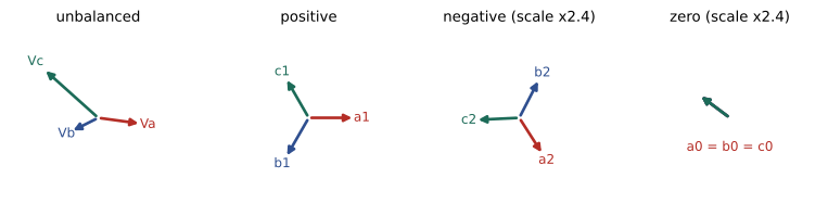
Unbalanced faults make the three phases unequal, so per-phase analysis no longer applies directly. In 1918, Charles Fortescue showed that any set of three unbalanced phasors can be written as the sum of three balanced sets: a positive-sequence set (same rotation as the system, a-b-c), a negative-sequence set (opposite rotation, a-c-b) and a zero-sequence set (three equal phasors in phase). With the operator \(a = 1\angle 120°\),
and the inverse transformation gives \(V_0 = \tfrac13(V_a + V_b + V_c)\), \(V_1 = \tfrac13(V_a + aV_b + a^2V_c)\) and \(V_2 = \tfrac13(V_a + a^2V_b + aV_c)\). The value of the transformation is that, in a balanced network, the three sequences do not interact: positive-sequence currents produce only positive-sequence voltage drops, and so on. Each sequence has its own network, which can be analyzed separately, and the unbalance is confined to the fault point.
Sequence networks
Each component has a sequence impedance:
- Positive sequence: the normal impedances used in load flow and three-phase fault studies; generators appear as voltage sources behind \(X_d''\).
- Negative sequence: for lines and transformers, equal to the positive-sequence impedance; for rotating machines, somewhat different, and there are no negative-sequence sources.
- Zero sequence: zero-sequence currents are equal in all three phases and must return through ground or neutral conductors, so zero-sequence impedance depends on grounding. For overhead lines it is typically two to four times the positive-sequence value because of the earth return path. Transformer connections are decisive: a grounded-wye winding passes zero-sequence current, a delta winding circulates it internally but blocks it from the lines, and an ungrounded wye blocks it entirely. A delta-wye grounded transformer therefore isolates the zero-sequence networks on its two sides.
Any neutral grounding impedance \(Z_n\) appears as \(3Z_n\) in the zero-sequence network, because all three phases' zero-sequence currents flow through it.
Unbalanced fault formulas
Connecting the sequence networks at the fault point according to the fault type gives the fault currents. With Thévenin sequence impedances \(Z_1\), \(Z_2\) and \(Z_0\) at the fault bus and prefault voltage \(V_f\):
| Fault | Sequence network connection | Fault current |
|---|---|---|
| Three-phase | Positive sequence only | \(I_a = V_f/Z_1\) |
| Single line-to-ground (phase a) | All three in series | \(I_a = 3V_f/(Z_1 + Z_2 + Z_0)\) |
| Line-to-line (b-c) | Positive and negative in parallel opposition | \(|I_b| = |I_c| = \sqrt3\,V_f/|Z_1 + Z_2|\) |
| Double line-to-ground (b-c-g) | Positive in series with negative and zero in parallel | \(I_1 = V_f/(Z_1 + Z_2 \| Z_0)\) |
import numpy as np

a = np.exp(2j * np.pi / 3)
A = np.array([[1, 1, 1], [1, a ** 2, a], [1, a, a ** 2]])      # phase = A @ (zero, positive, negative)

Z1 = Z2 = 0.1354j                         # Thevenin sequence impedances at bus 4 (pu)
Vf = 1.0
print(f"three-phase fault:   |Ia| = {abs(Vf / Z1):.2f} pu")

for label, Z0 in [("Z0 = 0.10 (solidly grounded, low Z0)", 0.10j),
                  ("Z0 = 0.30 (higher zero-sequence impedance)", 0.30j),
                  ("Z0 = 0.30 + 3 x 0.10 neutral reactor", 0.60j)]:
    I0 = I1 = I2 = Vf / (Z1 + Z2 + Z0)                          # single line-to-ground, phase a
    Iabc = A @ np.array([I0, I1, I2])
    print(f"SLG, {label}: |Ia| = {abs(Iabc[0]):.2f} pu, |Ib| = {abs(Iabc[1]):.2f}, |Ic| = {abs(Iabc[2]):.2f}")

I1 = Vf / (Z1 + Z2); I2 = -I1                                    # line-to-line, phases b and c
Iabc = A @ np.array([0, I1, I2])
print(f"line-to-line fault: |Ib| = |Ic| = {abs(Iabc[1]):.2f} pu  (= sqrt(3)/2 of the three-phase value)")

Z0 = 0.10j                                                       # double line-to-ground, phases b and c
I1 = Vf / (Z1 + Z2 * Z0 / (Z2 + Z0)); V1 = Vf - Z1 * I1
I2 = -V1 / Z2; I0 = -V1 / Z0
Iabc = A @ np.array([I0, I1, I2])
print(f"double line-to-ground: |Ib| = {abs(Iabc[1]):.2f} pu, |Ic| = {abs(Iabc[2]):.2f} pu, ground current = {abs(3 * I0):.2f} pu")three-phase fault: |Ia| = 7.39 pu SLG, Z0 = 0.10 (solidly grounded, low Z0): |Ia| = 8.09 pu, |Ib| = 0.00, |Ic| = 0.00 SLG, Z0 = 0.30 (higher zero-sequence impedance): |Ia| = 5.26 pu, |Ib| = 0.00, |Ic| = 0.00 SLG, Z0 = 0.30 + 3 x 0.10 neutral reactor: |Ia| = 3.45 pu, |Ib| = 0.00, |Ic| = 0.00 line-to-line fault: |Ib| = |Ic| = 6.40 pu (= sqrt(3)/2 of the three-phase value) double line-to-ground: |Ib| = 7.80 pu, |Ic| = 7.80 pu, ground current = 8.94 pu
With a low zero-sequence impedance, as on a solidly grounded transmission system near grounded-wye transformers, the SLG fault current exceeds the three-phase value. Raising \(Z_0\), or adding a neutral reactor that contributes \(3Z_n\), reduces it substantially. A line-to-line fault always gives \(\sqrt3/2\), or 87%, of the three-phase current when \(Z_2 = Z_1\).
Worked problem
Single line-to-ground fault by hand
At a 69 kV bus, \(Z_1 = Z_2 = j0.08\) pu and \(Z_0 = j0.05\) pu on a 100 MVA base. Find the SLG and three-phase fault currents in kA.
Show solution
- Base current: \(100 \times 10^6/(\sqrt3 \times 69{,}000) = 837\) A.
- Three-phase: \(1/0.08 = 12.5\) pu, or 10.5 kA.
- SLG: \(3/(0.08 + 0.08 + 0.05) = 3/0.21 = 14.3\) pu, or 12.0 kA.
Answer: The SLG fault current, 12.0 kA, exceeds the three-phase current of 10.5 kA because \(Z_0 < Z_1\). Breaker ratings must cover whichever is larger.
System grounding
How the neutral of a system is connected to ground controls ground fault current and overvoltages:
- Solidly grounded: neutrals connected directly to ground. Ground fault currents are high, so faults are detected and cleared quickly, and phase-to-ground voltages on the unfaulted phases stay close to normal. Used on transmission and most low-voltage systems.
- Resistance grounded: a resistor in the neutral limits ground fault current, commonly to 200 to 2000 A for low-resistance grounding at medium voltage or to under 10 A for high-resistance grounding. High-resistance grounding is used in industrial plants and some data center medium-voltage and 600 V or 480 V systems, because the first ground fault does not trip the supply and can be located and repaired at a convenient time.
- Ungrounded: no intentional connection. The first ground fault draws only small capacitive current, but the unfaulted phases rise to line-to-line voltage relative to ground, and intermittent arcing faults can cause severe overvoltages. Now rarely used for new systems.
In the US, the NEC permits high-impedance grounding of 480 V to 1000 V systems where qualified persons service the installation, ground detectors are installed and line-to-neutral loads are not served (250.36), and requires solid grounding of systems that supply line-to-neutral loads.
Equipment ratings and protection
Fault studies determine whether equipment can survive and interrupt the currents it may see:
- Circuit breakers have a rated short-circuit (interrupting) current, defined for a stated \(X/R\) ratio, and a close-and-latch (making) rating for the first asymmetrical peak. Where the actual \(X/R\) exceeds the rating basis, the calculated current is multiplied by a correction factor before comparison.
- Switchgear, bus duct and transformers have short-time withstand ratings, the current they can carry for a stated time (commonly 0.5 to 3 s) without mechanical or thermal damage. Electromagnetic forces scale with the square of the peak current.
- Fuses and low-voltage breakers have interrupting ratings that must exceed the available fault current at their location, as checked in ELEC-120 and DCE-310.
Fault growth is a recurring problem: as new generation and lower-impedance connections are added, fault levels rise until existing breakers are under-rated, requiring replacement, current-limiting reactors or bus splitting. Inverter-based resources, by contrast, contribute only about 1.1 to 1.5 times their rated current to a fault, which keeps fault levels low but makes protection that relies on large fault currents harder to set.
Protective relays use fault study results directly. Overcurrent relays are set above maximum load and below minimum fault current, and graded in time so that the device nearest the fault operates first (coordination). Distance relays on transmission lines measure the apparent impedance \(V/I\), which during a fault is proportional to the distance to the fault. Differential relays compare currents entering and leaving a transformer, generator or bus and trip when they differ. These are developed in the protection course that follows this one.
Worked problem
Checking a breaker rating
A 4.16 kV breaker is rated 40 kA interrupting at an \(X/R\) of 17. The calculated symmetrical fault current at its location is 31 kA, with an \(X/R\) of 25, for which the manufacturer's multiplying factor is 1.08. Is the breaker adequate?
Show solution
- Adjusted duty: \(31 \times 1.08 = 33.5\) kA.
- Compare with the rating: \(33.5 < 40\) kA, leaving a 16% margin.
Answer: Yes, with margin. Without the \(X/R\) correction the margin would appear larger than it is; with planned additions that raise the fault level by 20%, the duty would reach 40.2 kA and exceed the rating.
Lesson 10 applies these methods to whole networks with sequence bus impedance matrices, transformer phase shifts, open conductors and the standard calculation methods used for equipment ratings.
Common mistakes
MistakeAssuming the three-phase fault is always the largest.
InsteadWhere Z₀ < Z₁, single line-to-ground faults exceed three-phase faults; check both.
MistakeUsing synchronous reactance for breaker duty calculations.
InsteadUse subtransient reactance for the first cycles; synchronous reactance greatly underestimates initial current.
MistakeIgnoring the DC offset and X/R ratio when checking breakers.
InsteadApply X/R multiplying factors; asymmetry raises both making and interrupting duty.
MistakeCarrying zero-sequence current through a delta winding to the other side.
InsteadDelta and ungrounded windings block zero sequence between the two sides.
MistakeForgetting the factor of 3 for neutral grounding impedance.
InsteadZ_n appears as 3Z_n in the zero-sequence network.
Summary and key terms
- SLG faults are most common; three-phase faults are rarest but usually set equipment ratings.
- Fault current has a decaying DC offset (time constant X/ωR) and, near generators, a decaying AC component (X″d, X′d, X_d).
- Three-phase fault current: I_f = V_f/Z_th; fault MVA = S_b/Z_th,pu.
- Z_bus = Y_bus⁻¹ gives fault currents (V_f/Z_kk) and voltages (V_f(1 − Z_ik/Z_kk)) at all buses.
- Symmetrical components decompose unbalanced phasors into positive, negative and zero sequences that do not interact in a balanced network.
- Zero-sequence impedance depends on grounding and transformer connections; neutral impedance appears as 3Z_n.
- SLG: I = 3V_f/(Z₁ + Z₂ + Z₀); LL: √3 V_f/(Z₁ + Z₂); DLG: positive in series with negative ∥ zero.
- Solid, resistance and ungrounded systems trade fault current against overvoltage and continuity.
- Breakers, switchgear and fuses must be rated for the calculated duty including X/R effects; relays are set from fault study results.
- Bolted fault
- A fault with zero impedance at the fault point.
- DC offset
- The decaying unidirectional component of asymmetrical fault current.
- X/R ratio
- The ratio of reactance to resistance, setting the DC decay rate.
- Subtransient reactance
- Generator reactance governing current in the first few cycles of a fault.
- Fault level
- Three-phase short-circuit MVA at a bus.
- Bus impedance matrix
- The inverse of the bus admittance matrix; its diagonal gives Thévenin impedances.
- Symmetrical components
- Positive, negative and zero-sequence sets that sum to an unbalanced set.
- Sequence network
- The equivalent network for one sequence component.
- Zero sequence
- Three equal in-phase components; it flows only with a ground or neutral return.
- Solidly grounded
- A system with neutrals connected directly to ground.
- High-resistance grounding
- Grounding through a resistor that limits ground fault current to a few amperes.
- Interrupting rating
- The maximum fault current a device can safely interrupt.
- Short-time withstand
- The current equipment can carry for a stated time without damage.
- Distance relay
- A relay that trips based on the apparent impedance to a fault.
Practice problems
Work each problem on paper first, then reveal the answer to check.
What is the DC time constant of a fault with X/R = 20 at 60 Hz?
Show answer
20/(2π × 60) = 53 ms.
A 138 kV bus has a fault level of 3000 MVA. What is the Thévenin impedance on 100 MVA, and the fault current?
Show answer
0.0333 pu; I_b = 418 A; I_f = 30 × 418 = 12.6 kA.
A 2000 kVA, 5.75% transformer fed from a 250 MVA source supplies 480 V. Find the secondary fault current.
Show answer
On 2 MVA: source 0.008, transformer 0.0575, total 0.0655; I_b = 2406 A; I_f = 36.7 kA.
In a Z_bus, Z_kk = j0.12 and Z_ik = j0.04. What is the voltage at bus i during a bolted fault at bus k?
Show answer
1 − 0.04/0.12 = 0.667 pu.
Find the symmetrical components of Va = 1∠0°, Vb = 0, Vc = 0.
Show answer
V₀ = V₁ = V₂ = 1/3.
Why does a delta-wye grounded transformer block zero-sequence current from the delta side?
Show answer
Zero-sequence currents circulate inside the delta winding and cannot flow in the delta-side lines.
With Z₁ = Z₂ = j0.10 and Z₀ = j0.25, compare SLG and three-phase fault currents.
Show answer
Three-phase 10 pu; SLG 3/0.45 = 6.67 pu.
A neutral reactor of j0.05 pu is added to the previous system. What is the new SLG current?
Show answer
Z₀ effective 0.25 + 0.15 = 0.40; 3/0.60 = 5.0 pu.
What fraction of the three-phase fault current is a line-to-line fault when Z₂ = Z₁?
Show answer
√3/2 ≈ 0.866.
Why is high-resistance grounding attractive in critical facilities?
Show answer
The first ground fault draws only a few amperes and need not trip the supply, allowing it to be located and repaired without an outage.
Lesson quiz · 5 questions
Score 60% or more to complete this lesson.
Create a free account to save your progress, take quizzes and earn a certificate.