
ELE-340 · Lesson 8 of 12 · 26 min
Stability and frequency compensation
Every benefit of negative feedback depends on the feedback really being negative. At low frequencies it is. But each pole in the loop adds phase lag, up to 90° per pole, and at some frequency the total lag of the loop can reach 180°. There the returned signal adds to the input instead of subtracting from it. If the loop gain is still at least 1 at that frequency, the amplifier supplies its own input and oscillates. This lesson explains the condition with Bode plots of the loop gain, defines gain margin and phase margin, connects phase margin to the overshoot and ringing seen on an oscilloscope, and covers the standard ways of compensating a loop: dominant-pole, Miller, lead and lag compensation, and the special problem of capacitive loads.
The topic became urgent on Leo's bench. The first prototype of the APS-2 receiver used an op amp to drive a 10 nF filter capacitor at the converter input, and its output, which should have been a clean tone, showed a burst of ringing at every edge, at a frequency near 700 kHz. Nothing was wrong with the parts. The loop had too little phase margin.
When feedback becomes positive
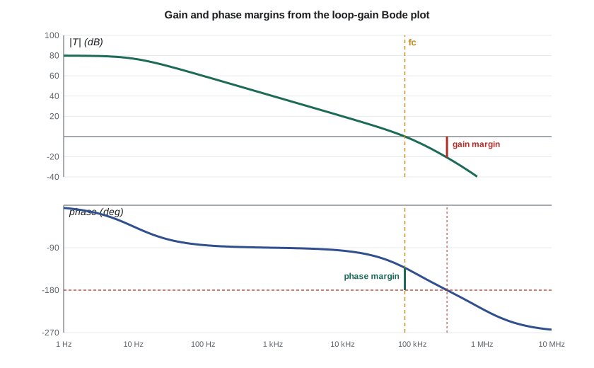
The closed-loop gain A_f = A/(1 + T) becomes infinite if T = −1, that is, if the loop gain has a magnitude of 1 and a phase of −180° at the same frequency. In terms of poles, the closed-loop poles are the roots of 1 + T(s) = 0, and the amplifier is stable only if all of them lie in the left half of the s-plane. For loops with ordinary minimum-phase transfer functions, a practical test follows from the Bode plot of T: find the crossover frequency f_c where |T| = 1, and check the phase there. If the phase lag at f_c is less than 180°, the loop is stable.
The phase margin PM is how far the phase at crossover is from −180°; the gain margin GM is how far the loop gain is below 1 at the frequency f_180 where the phase reaches −180°, usually quoted in decibels. A loop with one pole can never reach −180° and is always stable. A loop with two poles approaches −180° only at infinite frequency, so it is stable but can have a very small phase margin. A loop with three or more poles can reach −180° at a finite frequency and oscillate if the loop gain is still above 1 there.
Phase margin and the step response
Phase margin is more than a pass-fail test; it predicts how the closed-loop amplifier will behave. A loop with a dominant pole and one other pole gives a closed-loop response like a second-order system, whose damping depends on the phase margin. Low phase margin means a peak in the closed-loop frequency response just below f_c and overshoot and ringing in the step response; very low phase margin means a long ring at a frequency near f_c, exactly what Leo saw. The code below computes, for a two-pole loop, the phase margin, the damping ratio, the step overshoot and the frequency-response peak as the second pole moves relative to the loop's unity-gain frequency.
import math, cmath
def loop(f, fu, p2):
    """Loop gain with a dominant pole far below and a second pole p2: T = fu/(jf) / (1 + jf/p2)."""
    return fu / (1j * f) / (1 + 1j * f / p2)
def crossover(fu, p2):
    lo, hi = fu * 1e-4, fu * 10
    for _ in range(200):
        m = math.sqrt(lo * hi)
        if abs(loop(m, fu, p2)) > 1: lo = m
        else: hi = m
    return m
fu = 1.0
print(" p2/fu   PM(deg)  zeta  overshoot  peaking")
for r in (0.25, 0.5, 0.7, 1, 2, 3, 4):
    fc = crossover(fu, r)
    pm = 180 + math.degrees(cmath.phase(loop(fc, fu, r)))
    zeta = 0.5 * math.sqrt(r)                 # closed loop: s^2/(wu*wp2) + s/wu + 1
    os_ = 100 * math.exp(-math.pi * zeta / math.sqrt(1 - zeta ** 2)) if zeta < 1 else 0.0
    pk = 20 * math.log10(1 / (2 * zeta * math.sqrt(1 - zeta ** 2))) if zeta < 0.707 else 0.0
print(f"{r:5.2f} {pm:7.1f} {zeta:5.2f} {os_:7.1f} % {pk:5.2f} dB")p2/fu PM(deg) zeta overshoot peaking 0.25 28.0 0.25 44.4 % 6.30 dB 0.50 38.7 0.35 30.5 % 3.59 dB 0.70 44.8 0.42 23.5 % 2.38 dB 1.00 51.8 0.50 16.3 % 1.25 dB 2.00 65.5 0.71 4.3 % 0.00 dB 3.00 72.4 0.87 0.4 % 0.00 dB 4.00 76.3 1.00 0.0 % 0.00 dB
The output gives the rules of thumb that designers carry in their heads. A phase margin of about 28° gives over 40 percent overshoot and a 6 dB peak; about 45° gives roughly 23 percent overshoot and over 2 dB of peaking; about 52° gives 16 percent; about 65° gives only 4 percent and no peaking; and above 75° there is essentially no overshoot. Most op amp circuits are designed for 45° to 60°, power and audio amplifiers usually for 60° or more, so that tolerances, temperature and unexpected loads cannot erode the margin to zero. A margin of about 15°, as on Leo's prototype, gives ringing near the crossover frequency that dies away slowly.
Reading stability from the op amp's Bode plot
For an op amp circuit, β is set by the feedback resistors and is usually independent of frequency, so the loop gain is the op amp's open-loop gain shifted down by 1/β. On a log plot, the crossover is where the open-loop gain curve meets the horizontal line at the closed-loop gain 1/β, which is called the noise gain. The larger the closed-loop gain, the lower the crossover and the more phase margin there is, because the crossover moves away from the op amp's second pole. The worst case is the voltage follower, β = 1, which crosses over at the highest frequency. A unity-gain-stable op amp is compensated so that even the follower has adequate margin; a decompensated op amp, sold for higher bandwidth, is stable only at noise gains above a stated minimum, such as 5 or 10.
Worked problem
Phase margin of the driver op amp
The driver op amp has A_0 = 2 × 10⁵, a dominant pole at 50 Hz (so f_u = 10 MHz) and a second pole at 20 MHz. Find the phase margin at a closed-loop gain of 11 and as a voltage follower.
Show solution
- Gain of 11: |T| = 1 where the open-loop gain is 11, near 10 MHz/11:
- \[f_c \approx 0.91\ \text{MHz} \qquad \text{PM} \approx 180 - 90 - \arctan\frac{0.91}{20} \approx 87^\circ\]
- Follower (β = 1): solve 10 MHz/(f √(1 + (f/20 MHz)²)) = 1:
- \[f_c \approx 9.1\ \text{MHz} \qquad \text{PM} \approx 90 - \arctan\frac{9.1}{20} \approx 66^\circ\]
Answer: At a gain of 11 the margin is almost 90°, and even as a follower it is about 66°. The op amp alone is comfortably stable. Something outside it must have eaten the margin on Leo's prototype.
Capacitive loads
An op amp's open-loop output resistance R_o, tens of ohms, forms a pole with any load capacitance C_L at f_L = 1/(2πR_oC_L). That pole sits inside the feedback loop, because the feedback is taken from the capacitor's terminal, and it adds phase lag at crossover. A few hundred picofarads of cable can upset a fast op amp; 10 nF upsets almost any.
Worked problem
Why Leo's prototype rang
The receiver op amp has R_o = 75 Ω and drives the 10 nF capacitor directly, with a noise gain of 4 (β = 0.25) and the same f_u = 10 MHz and 20 MHz second pole. Estimate the phase margin, and then the margin with a 47 Ω isolation resistor between the output and the capacitor, with feedback taken from the op amp's output pin.
Show solution
- \[f_L = \frac{1}{2\pi \times 75 \times 10\ \text{nF}} \approx 212\ \text{kHz}\]
- Without the load pole, f_c ≈ 2.5 MHz; with it, the loop gain falls faster and crossover moves to about 0.7 MHz:
- \[\text{PM} \approx 180 - 90 - \arctan\frac{0.7}{0.212} - \arctan\frac{0.7}{20} \approx 15^\circ\]
- With R_iso outside the loop, the load pole leaves the loop and PM returns to about 83°.
Answer: The 10 nF capacitor added a pole at about 212 kHz inside the loop, the crossover fell to about 700 kHz, and the phase margin dropped to roughly 15°, consistent with the ringing near 700 kHz. Moving the feedback connection to the op amp side of a 47 Ω isolation resistor removes the capacitor from the loop. The capacitor and resistor now form a simple low-pass filter after the loop, with a corner near 340 kHz, which suits the converter, whose anti-aliasing filter wanted that capacitor anyway.
The isolation resistor is the simplest fix but makes the output voltage depend slightly on the load current, because R_iso is outside the loop. Where that matters, designers use in-loop compensation: DC feedback is taken from the load side of R_iso for accuracy, and a small capacitor from the op amp's output to its inverting input closes a high-frequency loop that does not include the load pole. Many op amps also specify a maximum load capacitance, and some are designed to drive any capacitance stably, at the cost of bandwidth.
Compensation techniques
When a loop lacks margin, the designer changes the loop gain's shape so that it crosses 1 before the extra poles add too much phase. The main techniques are:
| Technique | What it does | Advantages | Costs |
|---|---|---|---|
| Dominant-pole (narrowbanding) | Adds a very low-frequency pole so |T| crosses 1 before the other poles matter | Simple; very robust | Bandwidth falls to roughly the next pole's frequency divided by the low-frequency loop gain |
| Miller compensation | A small capacitor across a gain stage creates the dominant pole and splits the poles apart | Small capacitor; much higher bandwidth than plain dominant-pole | Slew rate limited to I/C_c; right-half-plane zero in CMOS |
| Lead compensation | A capacitor across the feedback resistor adds a zero to β, giving phase lead near crossover | Recovers margin without losing low-frequency gain | Raises high-frequency noise gain; needs care with tolerances |
| Lag compensation | A series RC lowers the loop gain at high frequency only | Keeps the low-frequency loop gain | Slower settling tail from the pole-zero pair |
| Isolation or in-loop compensation | Removes a load pole from the loop | Fixes capacitive-load ringing | Output accuracy or bandwidth trade-off |
Plain dominant-pole compensation is wasteful: to give a 60° margin it must place the unity-gain crossover below the first non-dominant pole, and if that pole comes from a slow transistor the whole amplifier becomes slow. Miller compensation achieves the same stability with a capacitor a hundred times smaller and a much higher crossover, because pole splitting pushes the non-dominant pole up as the dominant one moves down. That is why nearly every op amp and the power amplifier of lesson 12 use it.
Worked problem
Lead compensation in a feedback network
An amplifier with R_f = 10 kΩ and R_g = 1 kΩ has a crossover near 1 MHz and only 45° of margin. A capacitor C_f across R_f adds a zero in β at 1/(2πR_fC_f) and a pole at 1/(2π(R_f ∥ R_g)C_f). Choose C_f to place the zero at 1 MHz, and estimate the phase lead gained at crossover.
Show solution
- \[C_f = \frac{1}{2\pi \times 10\,000 \times 10^{6}} \approx 16\ \text{pF} \qquad f_{pole} = \frac{1}{2\pi \times 909 \times 16\ \text{pF}} \approx 11\ \text{MHz}\]
- \[\Delta\phi \approx \arctan\frac{1}{1} - \arctan\frac{1}{11} \approx 45^\circ - 5^\circ = 40^\circ\]
Answer: About 16 pF across the feedback resistor adds roughly 40° of phase lead at 1 MHz, raising the margin from 45° to nearly 85° in this idealized estimate. In practice the zero also raises the loop gain slightly, moving crossover up and returning part of the lead, so the real improvement is somewhat smaller; Amara would confirm with simulation and a step test.
Measuring stability
On the bench, the quickest check is the small-signal step response: drive the amplifier with a small square wave, small enough that nothing slews, and measure overshoot and ringing with an oscilloscope and a low-capacitance probe. The overshoot table from the code translates the result into a phase margin. A more direct method measures the loop gain itself by injecting a small signal through a resistor or transformer inside the loop and comparing the voltages on either side, a technique due to Middlebrook that network analyzers automate. Symptoms of outright oscillation include a fuzzy or thick trace, an op amp that runs warm with no load, supply current higher than the datasheet's quiescent value, and problems that change when a finger or a probe touches the circuit. Leo's prototype showed only ringing, not oscillation; with the isolation resistor in place, the step response shows less than 5 percent overshoot.
Common mistakes
MistakeChecking stability with the open-loop gain alone.
InsteadStability depends on the loop gain T = Aβ; check the phase where |T| = 1.
MistakeAssuming a unity-gain-stable op amp is stable with any load.
InsteadLoad capacitance adds a pole inside the loop; check or isolate it.
MistakeUsing a decompensated op amp as a follower.
InsteadIt is stable only above its minimum noise gain; read the datasheet.
MistakeJudging stability with a large square wave.
InsteadLarge steps make the amplifier slew; use a small step so the response is linear.
Summary and key terms
- A feedback loop oscillates if |T| ≥ 1 where its phase reaches −180°.
- Phase margin is 180° plus the phase of T at crossover; gain margin is how far |T| is below 1 at −180°.
- Low phase margin causes peaking and overshoot: about 45° gives roughly 23 percent overshoot, 60° to 70° only a few percent.
- Higher closed-loop gain lowers crossover and increases margin; the follower is the worst case.
- Capacitive loads add a pole R_oC_L inside the loop; isolation resistors or in-loop compensation remove it.
- Dominant-pole, Miller, lead and lag compensation reshape the loop gain to restore margin.
- Measure stability with a small-signal step test or loop-gain injection.
- Phase margin
- 180° plus the phase of the loop gain at the frequency where its magnitude is 1.
- Gain margin
- The factor by which the loop gain is below 1 at the frequency where its phase reaches −180°.
- Crossover frequency
- The frequency at which the magnitude of the loop gain equals 1.
- Noise gain
- The reciprocal of β, the closed-loop gain seen by noise at the op amp's input.
- Decompensated op amp
- An op amp compensated for stability only above a minimum noise gain, in exchange for higher bandwidth.
- Isolation resistor
- A small resistor between an amplifier output and a capacitive load that removes the load pole from the loop.
- Lead compensation
- Adding a zero to the loop gain near crossover to increase phase margin.
Practice problems
Work each problem on paper first, then reveal the answer to check.
A loop has a phase of −135° at crossover. Find the phase margin.
Show answer
45°.
At the frequency where the loop's phase reaches −180°, |T| = 0.2. Find the gain margin in dB.
Show answer
20 log₁₀ 5 ≈ 14 dB.
An op amp with R_o = 50 Ω drives 2 nF. Where is the load pole?
Show answer
1/(2π × 50 × 2 nF) ≈ 1.6 MHz.
Why is a voltage follower the hardest gain setting to stabilize?
Show answer
β = 1, so crossover is at the highest frequency, closest to the op amp\'s non-dominant poles.
A step test shows 20 percent overshoot on a two-pole loop. Roughly what phase margin is that?
Show answer
Between about 45° and 52°.
A 4.7 kΩ feedback resistor needs a lead zero at 2 MHz. Find C_f.
Show answer
1/(2π × 4700 × 2 MHz) ≈ 17 pF.
Lesson quiz · 5 questions
Score 60% or more to complete this lesson.
Create a free account to save your progress, take quizzes and earn a certificate.