
ELE-340 · Lesson 7 of 12 · 26 min
Negative feedback and the four topologies
Transistor gain is large but unreliable: β varies by a factor of three between parts of one type, g_m follows current and temperature, and every stage distorts. Negative feedback turns that large, unreliable gain into a smaller gain set by resistors, with lower distortion, wider bandwidth and input and output resistances chosen by the designer. Harold Black's insight in the 1920s, made to solve distortion in long-distance telephone repeaters, is that if part of the output is subtracted from the input, the amplifier spends its excess gain correcting its own errors. This lesson develops the general feedback equation, quantifies each benefit and its cost, and classifies feedback amplifiers into four topologies by what they sense at the output and how they mix at the input.
Every amplifier in the APS-2 uses feedback. The receiver's gain of 4 is set by resistor ratios around an op amp; the preamplifier's gain of 25 likewise. The power amplifier, which Amara will design in lesson 12, wraps feedback around an output stage whose open-loop distortion would be clearly audible, so that the locator tone and voice messages come out clean. Before she can design it, she needs to know how much loop gain buys how much improvement.
The feedback equation
A feedback amplifier has a forward amplifier with gain A and a feedback network with transmission β. The feedback network samples the output x_o and returns x_f = βx_o, which is subtracted from the input x_s, leaving the error x_i = x_s − x_f to drive the amplifier. Then x_o = A(x_s − βx_o), so
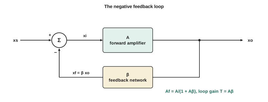
The quantity T = Aβ, the loop gain, is the gain around the loop: a signal leaving the summing junction is amplified by A and returned by β. The quantity 1 + T, the amount of feedback, appears in every result. When T is large, the closed-loop gain approaches 1/β and depends only on the feedback network, usually a pair of resistors, whose ratio can be held to 0.1 percent or better. In a non-inverting op amp circuit with feedback resistor R_f and ground resistor R_g, β = R_g/(R_f + R_g), so the familiar gain 1 + R_f/R_g is simply 1/β.
Worked problem
How precise is a feedback gain?
The APS-2 power-amplifier driver uses a non-inverting gain of 11 (R_f = 10 kΩ, R_g = 1 kΩ) around an op amp with A = 2 × 10⁵ at low frequency. Find A_f, its error from 11, and how much A_f changes if A falls by half.
Show solution
- \[\beta = \frac{1}{11} \qquad T = \frac{2\times10^{5}}{11} \approx 18\,180\]
- \[A_f = \frac{2\times10^{5}}{1 + 18\,180} \approx 10.99940 \;(\text{error } 0.0055\ \%)\]
- \[A = 10^{5}: \quad A_f = \frac{10^{5}}{1 + 9091} \approx 10.99879\]
Answer: The closed-loop gain is 11 to within 0.006 percent, and halving the op amp's gain changes it by only about 0.0055 percent, far less than the resistors' own tolerance. The amplifier's gain is now a property of two resistors.
Desensitivity and the cost of feedback
Differentiating the feedback equation shows how changes in A are suppressed:
A 1 + T of 1,000 makes the closed-loop gain a thousand times less sensitive to the forward gain. The price is gain itself: A_f is smaller than A by the same factor 1 + T. Feedback therefore makes sense only when gain is cheap, which it is: an op amp gives 100 dB for a few cents, and spending 80 dB of it on precision and linearity is a bargain. The second price is the possibility of instability, because the loop gain changes phase with frequency; lesson 8 deals with it.
Bandwidth extension
If the forward amplifier has a single pole, A(s) = A_0/(1 + s/ω_H), substituting into the feedback equation gives
Feedback divides the gain by 1 + T and multiplies the bandwidth by the same factor, leaving the gain-bandwidth product unchanged. That is why op amp circuits are designed with the GBW in mind: a 10 MHz op amp gives a 909 kHz bandwidth at a gain of 11 and a 100 kHz bandwidth at a gain of 100. Lower-frequency poles in the loop are pushed up the same way, which is how feedback flattens the response of an output stage.
Reduced distortion
Distortion generated inside the forward amplifier can be modeled as an unwanted signal added at its output. Feedback treats it like any other error and divides it by 1 + T. Equivalently, the amplifier needs only a small error signal to produce its output, so it operates over a small part of its nonlinear transfer curve. The improvement holds only while T is large, which means at frequencies where the loop gain is still high, and only while nothing clips: once the output stage saturates, A collapses, T collapses with it, and feedback cannot help. The code below models an amplifier whose output saturates smoothly, like a real output stage, and compares its distortion open-loop and with feedback at the same 8 V peak output.
import math
Vsat, A = 12.0, 2000.0          # smooth saturation at 12 V; small-signal forward gain 2000
beta = 1 / 11
f = lambda e: Vsat * math.tanh(A * e / Vsat)
N = 256
def thd(out):
    """Harmonic distortion of one period of samples via a direct DFT."""
    mags = []
    for k in range(1, 8):
        re = sum(out[n] * math.cos(2 * math.pi * k * n / N) for n in range(N))
        im = sum(out[n] * math.sin(2 * math.pi * k * n / N) for n in range(N))
        mags.append(2 * math.hypot(re, im) / N)
    return mags[0], math.sqrt(sum(m * m for m in mags[1:])) / mags[0]
def closed(x):
    lo, hi = -Vsat, Vsat         # solve y = f(x - beta*y) by bisection
    for _ in range(60):
        y = (lo + hi) / 2
        if y - f(x - beta * y) > 0: hi = y
        else: lo = y
    return y
def peak_for(fn, target):
    lo, hi = 0.0, 5.0
    for _ in range(50):          # find input amplitude giving the target output fundamental
        a = (lo + hi) / 2
        out = [fn(a * math.sin(2 * math.pi * n / N)) for n in range(N)]
        if thd(out)[0] > target: hi = a
        else: lo = a
    return a, out
a_ol, out_ol = peak_for(f, 8.0)
a_cl, out_cl = peak_for(closed, 8.0)
T = A * beta
print(f"loop gain T = {T:.0f}, 1 + T = {1+T:.0f}")
print(f"open loop:   input {a_ol*1e3:7.3f} mV peak, THD = {100*thd(out_ol)[1]:.2f} %")
print(f"closed loop: input {a_cl*1e3:7.1f} mV peak, THD = {100*thd(out_cl)[1]:.4f} %")
print(f"improvement = {thd(out_ol)[1]/thd(out_cl)[1]:.0f} times")loop gain T = 182, 1 + T = 183 open loop: input 4.550 mV peak, THD = 4.20 % closed loop: input 731.9 mV peak, THD = 0.0305 % improvement = 138 times
Open loop, an 8 V output from an amplifier that saturates at 12 V carries about 4 percent distortion, mostly third harmonic. With a loop gain of about 182, the same output carries about 0.03 percent, roughly 140 times less. The reduction falls short of 1 + T = 183 because the small-signal loop gain is not the gain at the peaks of the waveform, where the amplifier is already compressing; near clipping, the incremental A falls and so does the improvement, which is why feedback amplifiers clip abruptly rather than gradually.
What feedback does not do
Feedback cannot reduce noise that enters at the input along with the signal, because the loop cannot tell them apart; it also cannot reduce the input-referred noise of the first stage, since that noise is indistinguishable from an input signal. What it can reduce is noise and interference injected later in the loop. Hum on the output stage's supply rail, for example, is an error at the output and is divided by 1 + T, which is one reason a power amplifier with heavy feedback can run from a simple unregulated supply. Feedback also cannot fix an amplifier that is overdriven, and it cannot create gain where the loop gain has already fallen to 1.
The four topologies
A feedback amplifier senses either the output voltage (shunt sampling, the feedback network connected across the output) or the output current (series sampling, the network in series with the output loop), and mixes the feedback with the input either as a voltage in series with the input loop (series mixing) or as a current into the input node (shunt mixing). The four combinations stabilize four different gains, and each changes the input and output resistances by the factor 1 + T in a predictable direction:
| Topology (mixing–sampling) | Stabilized gain | Input resistance | Output resistance | Example |
|---|---|---|---|---|
| Series–shunt | Voltage gain v_o/v_s | Multiplied by 1 + T | Divided by 1 + T | Non-inverting op amp amplifier; voltage regulator |
| Shunt–series | Current gain i_o/i_s | Divided by 1 + T | Multiplied by 1 + T | Current amplifier; precision current source |
| Series–series | Transconductance i_o/v_s | Multiplied by 1 + T | Multiplied by 1 + T | Degenerated CE stage; voltage-to-current converter |
| Shunt–shunt | Transresistance v_o/i_s | Divided by 1 + T | Divided by 1 + T | Transimpedance photodiode amplifier; inverting op amp stage |
The pattern is easy to remember: series connections, whether at the input or the output, multiply the resistance there by 1 + T, and shunt connections divide it. A voltage amplifier should have a high input and low output resistance, so it uses series mixing and shunt sampling. A current source should have a high output resistance, so it samples current in series. The emitter-degenerated CE stage from Electronics I is a series–series feedback amplifier with β = R_E: its transconductance is g_m/(1 + g_m R_E), approaching 1/R_E, and its input resistance rises from r_π to r_π(1 + g_m R_E), which is the resistance-reflection rule seen as feedback.
Worked problem
Output resistance of the driver at audio frequencies
The driver op amp has an open-loop output resistance of 75 Ω and a GBW of 10 MHz. In the gain-of-11 circuit, find the closed-loop output resistance at 10 kHz.
Show solution
- Above the dominant pole, the open-loop gain is about f_u/f:
- \[A(10\ \text{kHz}) \approx \frac{10\ \text{MHz}}{10\ \text{kHz}} = 1000 \qquad T = \frac{1000}{11} \approx 91\]
- \[R_{of} = \frac{75}{1 + 91} \approx 0.82\ \Omega\]
Answer: At 10 kHz the driver's output resistance is under 1 Ω, so it drives the power stage's input without noticeable loss. At 100 kHz, where T is only about 9, the output resistance rises to about 7.5 Ω, and because T falls with frequency the output resistance rises with frequency: a feedback amplifier's output looks inductive. That inductive output, meeting a capacitive load, is one of the stability problems in the next lesson.
Analyzing a feedback amplifier
Real feedback networks are not ideal: they load the amplifier's input and output, and the amplifier may pass a little signal backward. The systematic method handles this by splitting the circuit into an A circuit and a β circuit. First identify the topology from how the feedback network connects at each end. Then form the A circuit by including the loading of the feedback network: at a shunt connection, the feedback network's port is left loading the node with the other port shorted; at a series connection, it is left with the other port open. Compute A, β and T, then A_f = A/(1 + T), and adjust the input and output resistances by 1 + T in the directions the table gives. For op amp circuits with large T, the shortcut A_f ≈ 1/β is usually all that is needed; the full method matters for transistor-level feedback pairs and for checking how much loop gain a design really has.
Worked problem
A transimpedance amplifier as shunt–shunt feedback
A photodiode amplifier uses an op amp with A = 10⁵ and a feedback resistor R_f = 100 kΩ from output to inverting input; the photodiode current enters the inverting input. Find the transresistance and the input resistance seen by the photodiode, given an open-loop input resistance much larger than R_f.
Show solution
- Feedback senses the output voltage and returns a current −v_o/R_f to the input node, so β = −1/R_f and A is a transresistance of about −A × R_f:
- \[T \approx A = 10^{5} \qquad R_M \approx -R_f = -100\ \text{k}\Omega\]
- \[R_{if} \approx \frac{R_f}{1 + A} \approx \frac{100\ \text{k}}{10^{5}} = 1\ \Omega\]
Answer: The amplifier converts current to voltage at −100 kΩ, or −0.1 V/µA, and presents only about 1 Ω to the photodiode, which therefore sits at nearly constant voltage: its capacitance is not charged and discharged by the signal, which is why transimpedance amplifiers are much faster than a photodiode driving a resistor.
Common mistakes
MistakeExpecting feedback to reduce the noise of the input stage.
InsteadInput-referred noise is unchanged; feedback reduces only errors and noise injected later in the loop.
MistakeAssuming the benefits of feedback are the same at all frequencies.
InsteadThey scale with 1 + T, which falls as the open-loop gain falls with frequency.
MistakeUsing feedback to clean up an amplifier that is clipping.
InsteadIn saturation A collapses and T with it; keep the output within its linear range.
MistakeMixing up which connections raise and which lower resistance.
InsteadSeries connections multiply by 1 + T; shunt connections divide by 1 + T.
Summary and key terms
- A_f = A/(1 + T), with loop gain T = Aβ; for large T, A_f ≈ 1/β.
- Sensitivity to changes in A is divided by 1 + T; the gain itself is divided by the same factor.
- For a single-pole amplifier, feedback multiplies bandwidth by 1 + T and keeps the gain-bandwidth product constant.
- Distortion and interference generated inside the loop are divided by 1 + T, while the loop gain lasts.
- Feedback does not reduce input noise and cannot correct clipping.
- Series–shunt, shunt–series, series–series and shunt–shunt stabilize voltage, current, transconductance and transresistance gain.
- Series connections multiply resistances by 1 + T; shunt connections divide them.
- Negative feedback
- Returning part of the output to subtract from the input, so that errors are corrected.
- Loop gain
- T = Aβ, the gain around the feedback loop.
- Amount of feedback
- 1 + T, the factor by which gain, sensitivity and distortion are reduced.
- Desensitivity
- The reduction in a closed-loop gain's sensitivity to changes in the forward gain.
- Series mixing
- Subtracting the feedback as a voltage in series with the input loop.
- Shunt sampling
- Sensing the output voltage with the feedback network connected across the output.
- Transimpedance amplifier
- A shunt–shunt feedback amplifier that converts an input current to an output voltage.
Practice problems
Work each problem on paper first, then reveal the answer to check.
A = 5,000 and β = 0.01. Find A_f and T.
Show answer
T = 50; A_f = 5000/51 ≈ 98.0.
For the amplifier above, A drops by 20 percent. By what percentage does A_f change?
Show answer
About 20/51 ≈ 0.39 percent.
An op amp with a 4 MHz GBW is used at a closed-loop gain of 20. Estimate the bandwidth.
Show answer
4 MHz/20 = 200 kHz.
An amplifier has an open-loop input resistance of 50 kΩ and T = 200 with series mixing. Find R_if.
Show answer
50 k × 201 ≈ 10 MΩ.
Which topology suits a precision current source driving a variable load?
Show answer
Series sampling at the output, so output resistance is multiplied by 1 + T (shunt–series or series–series).
An output stage adds 2 percent distortion open loop. With T = 400 at the signal frequency, estimate the closed-loop distortion.
Show answer
2 %/401 ≈ 0.005 %.
Lesson quiz · 5 questions
Score 60% or more to complete this lesson.
Create a free account to save your progress, take quizzes and earn a certificate.