
DCE-460 · Lesson 3 of 12 · 24 min
Power distribution efficiency
Every kilowatt-hour that reaches a server has passed through a chain of transformers, switchgear, uninterruptible power supplies, distribution units and the server's own power supply, and each stage converts a little of the energy to heat. In an older facility, losses in the electrical chain alone can reach 10 % or more of the IT load, and the heat they produce must then be removed by the cooling system, adding further energy. Modern designs cut these losses substantially. This lesson follows energy through the power chain, explains where losses occur and why they are worse at light load, examines UPS efficiency and operating modes, distribution voltages and server power supplies, and quantifies the savings from design and operating choices.
The power chain
A typical path from the utility to the processor includes:
- Medium-voltage switchgear and step-down transformers, converting utility voltage to the building's distribution voltage.
- Low-voltage switchgear and distribution boards.
- The UPS, which in double-conversion mode rectifies AC to DC (charging batteries) and inverts it back to clean AC.
- Power distribution units (PDUs), often with transformers stepping voltage down further for the racks, and rack PDUs.
- The server power supply unit (PSU), converting AC to the DC voltages used inside the server, followed by voltage regulators on the motherboard.
Each conversion has an efficiency below 100 %. Multiplying them gives the efficiency of the chain: a chain of a 98.5 % transformer, a 95 % UPS and a 98.5 % PDU delivers about 92 % of the input energy to the IT equipment, and the rest becomes heat.
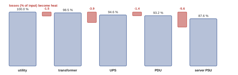
Why light load is inefficient
Most electrical equipment has two kinds of losses. Fixed (no-load) losses, such as transformer core magnetization and the control electronics and fans in a UPS, occur whatever the load. Variable (load) losses, such as resistive heating in windings and conductors, grow roughly with the square of the current. As a result, efficiency is poor at light load, where fixed losses dominate, peaks somewhere between about 40 % and 75 % of rating, and falls slightly at full load.
Redundancy makes light load the norm. In a 2N design, each of two UPS systems must be able to carry the whole load, so each normally runs below 50 %, and in a new or partly occupied facility, perhaps at 20 or 30 %. A design that is efficient at full load may therefore operate for years in its least efficient region. Modular UPS systems that switch off unneeded modules, right-sized transformers and phased build-outs help keep equipment in its efficient range.
import numpy as np

# UPS efficiency curve (double conversion) by per-unit load, interpolated from datasheet points
pts_load = [0.10, 0.25, 0.50, 0.75, 1.00]
pts_eff = [0.880, 0.940, 0.960, 0.965, 0.962]

def ups_eff(load):
    return np.interp(load, pts_load, pts_eff)

def chain_loss(it_kW, ups_kW_each, n_ups, transformer_eff=0.985, pdu_eff=0.985, eco=False):
    load_each = it_kW / pdu_eff / (ups_kW_each * n_ups)
    eff_ups = 0.99 if eco else ups_eff(load_each)
    supply = it_kW / pdu_eff / eff_ups / transformer_eff
    return supply - it_kW, load_each, eff_ups

it_kW = 1200
for label, n, eco in [("2N, two 2000 kW systems", 2, False), ("N+1, three 1000 kW modules", 3, False),
                      ("2N with eco-mode", 2, True)]:
    size = 2000 if n == 2 else 1000
    loss, load, eff = chain_loss(it_kW, size, n, eco=eco)
    print(f"{label:<30} UPS load {load:5.0%}, UPS eff {eff:.3f}, chain loss {loss:6.1f} kW, "
f"{loss * 8760 / 1000:,.0f} MWh/yr")2N, two 2000 kW systems UPS load 30%, UPS eff 0.944, chain loss 109.7 kW, 961 MWh/yr N+1, three 1000 kW modules UPS load 41%, UPS eff 0.952, chain loss 98.5 kW, 863 MWh/yr 2N with eco-mode UPS load 30%, UPS eff 0.990, chain loss 49.3 kW, 432 MWh/yr
In the 2N arrangement, each UPS runs at 30 % load with an efficiency of about 94 %, and the chain loses about 110 kW, nearly 1,000 MWh a year. An N+1 arrangement of smaller modules runs each at about 41 % and saves around 100 MWh a year. Operating the 2N system in eco-mode (described below) roughly halves the chain loss, saving over 500 MWh a year, before counting the cooling energy that no longer has to remove that heat.
UPS operating modes
Double-conversion (online) UPS operation gives the best power quality, isolating the load from every disturbance on the supply, but it converts all energy twice. Modern UPS systems offer higher-efficiency modes:
- Eco-mode (or bypass mode): the load runs from the utility through the static bypass, with the inverter on standby; on a disturbance, the UPS transfers to inverter within a few milliseconds. Efficiency is about 99 %, but the load is exposed to minor supply disturbances and depends on fast transfer.
- Advanced or active eco-modes: the inverter runs in parallel with the bypass, filtering harmonics and correcting power factor while most power flows through the bypass, with efficiencies around 98.5 to 99 % and faster response.
- Module management: in modular UPS systems, idle modules are switched off so that the remaining ones run at higher, more efficient load, while keeping enough capacity for redundancy.
Operators have historically been cautious about eco-modes because of the small risk to the IT load. Today, many hyperscale operators use them routinely, and server power supplies tolerate brief transfers well. The decision should be based on the site's power quality, testing of transfer behavior during commissioning (DCE-450, Lesson 5), and the customer's risk tolerance.
Transformers and distribution voltage
Transformers are highly efficient, often 98 to 99 % at moderate load, but they run continuously, so small efficiency differences add up. Codes and regulations set minimum efficiencies for distribution transformers.
In the United States, the Department of Energy sets minimum efficiencies for distribution transformers under 10 CFR Part 431, with updated standards adopted in 2024 for future production. US facilities often distribute at 480 V and step down to 208Y/120 V for IT loads, a stage that designers can avoid by distributing 415Y/240 V directly to racks, since most server power supplies accept 240 V.
Higher distribution voltages reduce current and therefore resistive losses in cables and busway, and eliminating a transformer stage removes its losses entirely. Many modern data centers distribute at 415Y/240 V to the rack, and some large operators use 48 V DC distribution within racks, converting once from AC to DC at rack-level power shelves. Direct current distribution at higher voltages (for example 380 V DC) has been demonstrated and can remove conversion stages, but it requires specialized equipment and protection.
Server power supplies
Every server has its own power supply, and their combined losses can rival the UPS. Efficiency is rated by programs such as 80 PLUS, whose Titanium level requires about 94 to 96 % efficiency across a range of loads (and 90 % at 10 % load) for 230 V internal-redundant supplies. Like UPS systems, PSUs are least efficient at light load, and servers with redundant power supplies sharing the load run each supply at half load or less. Configuring redundant supplies so that one carries the load while the other stands by, where the server supports it, and choosing supplies sized for the actual server configuration rather than the maximum, improve efficiency. Higher input voltage (240 V rather than 120 V) also improves PSU efficiency by about one percentage point.
Other electrical overheads
Several smaller loads add up: generator block heaters that keep diesel engines warm for fast starts (often several kilowatts per generator, running continuously), battery room heating and cooling, lighting, security systems, and office space within the facility. Each deserves attention: block heaters can be thermostatically controlled and insulated, lighting can use LEDs with occupancy controls, and battery technologies with wider temperature tolerance, such as lithium-ion, reduce the need for tightly controlled battery rooms.
Worked problem
Valuing a UPS efficiency improvement
A facility's UPS losses are 150 kW at its average load. Switching to an advanced eco-mode would cut them to 40 kW. Each kilowatt of heat removed requires about 0.25 kW of cooling energy. Electricity costs 0.10 per kWh. What is the annual saving in energy and cost?
Show solution
- Electrical saving: 150 − 40 = 110 kW.
- Cooling saving: 110 × 0.25 = 27.5 kW. Total: 137.5 kW.
- Annual energy: 137.5 × 8,760 ≈ 1,200 MWh; cost saving ≈ 120,000 a year.
Answer: About 1,200 MWh and 120,000 a year, plus the avoided emissions at the grid's carbon intensity. Savings in electrical losses are worth more than their face value because each removed watt of loss also removes cooling energy. The decision still requires assessing the reliability implications and testing transfer behavior.
Measuring electrical losses
Losses cannot be managed unless they are measured. Modern UPS systems, transformers with monitoring, and power meters at switchboards and PDUs allow the electrical chain to be broken down: comparing energy into and out of each stage gives its actual operating efficiency, which often differs from datasheet values because of real load levels, harmonics and temperature. An electrical pPUE (total electrical input divided by IT energy, counting only electrical losses) for each hall is a useful operational metric. Metering also reveals unexpected loads, such as heaters left on in battery rooms or unused PDUs drawing no-load losses, which are easy to fix once seen.
Batteries and energy storage
Energy storage in the UPS also affects efficiency. Valve-regulated lead-acid batteries need cool, tightly controlled rooms (around 20 to 25 °C) to reach their rated life, which means dedicated cooling energy, and they must be replaced every few years. Lithium-ion batteries tolerate warmer temperatures, last longer and occupy less space, reducing both cooling energy and replacement materials, though they require careful fire risk management. Larger battery systems can also provide grid services and support clean energy matching (Lesson 8), turning a backup asset into an active part of the energy system. Battery charging and float losses are small but continuous and should be included in electrical loss estimates.
Finally, power quality affects efficiency: harmonic currents from IT power supplies increase transformer and cable heating, and poor power factor raises currents throughout the chain. Modern IT power supplies with active power factor correction, and UPS systems that present a clean input to the grid, keep these losses small.
Taken together, these measures can bring the electrical chain's losses from 10 % or more of IT load in older facilities to around 4 to 6 % in modern ones, a saving that also reduces the cooling plant's work.
Common mistakes
MistakeSelecting equipment on full-load efficiency only.
InsteadCompare efficiency at the actual operating load, often 20 to 50 %.
MistakeOversizing UPS and transformers for distant future load.
InsteadUse modular, phased capacity that keeps equipment in its efficient range.
MistakeIgnoring the cooling cost of electrical losses.
InsteadValue each kW of loss saved plus the cooling it avoids.
MistakeRejecting eco-modes without evaluation.
InsteadAssess power quality and test transfers before deciding.
MistakeLeaving generator block heaters and lighting uncontrolled.
InsteadControl and insulate small continuous loads.
Summary and key terms
- Losses occur at each conversion: transformers, UPS, PDUs and server power supplies.
- Fixed losses make equipment inefficient at light load, which redundancy makes common.
- Modular and right-sized equipment keeps operating points efficient.
- Eco-modes raise UPS efficiency to about 99 % with a small change in power quality exposure.
- Higher distribution voltages and fewer transformer stages reduce losses.
- Efficient, right-sized server power supplies at higher voltage matter.
- Every kW of electrical loss saved also saves cooling energy.
- Double conversion
- UPS operation rectifying and inverting all power.
- Eco-mode
- UPS operation through the bypass with the inverter on standby.
- No-load loss
- Losses present regardless of load.
- Load loss
- Losses that grow with current.
- Modular UPS
- A UPS built from modules that can be switched in and out.
- Distribution voltage
- The voltage at which power is carried within the building.
- Power supply unit
- The server component converting AC to internal DC voltages.
- 80 PLUS
- A certification program for power supply efficiency.
- Block heater
- A heater keeping a standby engine warm.
- Chain efficiency
- The product of the efficiencies of all conversion stages.
Practice problems
Work each problem on paper first, then reveal the answer to check.
What is the chain efficiency of 98.5 %, 95 % and 98.5 % stages?
Show answer
About 92.2 %.
Why is equipment inefficient at light load?
Show answer
Fixed losses are large relative to the power delivered.
Why do 2N UPS systems often run at light load?
Show answer
Each must carry the whole load alone, so each normally carries less than half.
From the output, how much does eco-mode save in the 2N case?
Show answer
About 60 kW, roughly 530 MWh a year.
What is the trade-off of eco-mode?
Show answer
Higher efficiency but exposure to minor supply disturbances and reliance on fast transfer.
Why does higher distribution voltage reduce losses?
Show answer
It reduces current and resistive losses, and can remove a transformer stage.
What efficiency does 80 PLUS Titanium require at 10 % load?
Show answer
About 90 %.
How much does 240 V input typically improve PSU efficiency over 120 V?
Show answer
About one percentage point.
A 50 kW loss reduction with 0.3 kW of cooling per kW of heat saves how much power in total?
Show answer
65 kW.
Name two small continuous electrical overheads.
Show answer
Generator block heaters, battery room conditioning, lighting, security, offices.
Lesson quiz · 5 questions
Score 60% or more to complete this lesson.
Create a free account to save your progress, take quizzes and earn a certificate.