
DCE-430 · Lesson 9 of 12 · 32 min
Prefabrication and modular construction
Speed to market is one of the strongest forces in data center construction. Each month a facility is delayed is a month of lost revenue on capacity worth hundreds of millions of dollars, and demand for AI computing has pushed owners to deliver large campuses in 12 to 18 months instead of the traditional two to three years. One of the main ways to build faster is to move work off site: manufacturing building components, electrical and mechanical systems, and even complete data halls in factories, then shipping and assembling them on site. This lesson covers the forms of prefabrication, its advantages and limits, transport and lifting constraints, approvals, interfaces and tolerances, and how modular strategies support phasing.
Why prefabricate
Prefabrication and modular construction (often described as design for manufacture and assembly, DfMA) offer:
- Speed: factory work proceeds in parallel with site work (grading, foundations, utilities), so the overall schedule shortens; modules arrive ready to set and connect.
- Quality: factories offer controlled conditions, jigs, repeatable processes and factory acceptance testing (FAT) before shipment, so fewer defects reach the site.
- Labor: skilled trades are scarce in many data center markets; factories use labor more efficiently and in locations where it is available.
- Safety: less work at height and in congested sites.
- Repeatability: standard modules reused across campuses capture learning and simplify maintenance.
The trade-offs are less flexibility to change designs late, larger up-front design effort, transport costs and limits, the need for precise interfaces, and dependence on factory capacity, which itself became a constraint as demand surged.
Forms of prefabrication
Prefabrication ranges from components to whole buildings:
| Level | Examples | Typical use in data centers |
|---|---|---|
| Components | Precast concrete walls and double tees, steel frames, wall panels, roof cassettes | Faster building shell |
| Assemblies (MEP racks) | Pre-assembled pipe, cable tray and busway racks; prefabricated containment | Data hall fit-out, corridors |
| Skids | Pump skids, generator sets with enclosures and fuel tanks, cooling distribution units | Plant rooms and yards |
| Prefabricated electrical rooms (eHouses, power modules) | Switchgear, UPS and batteries in a factory-built enclosure | Electrical capacity delivered as blocks (for example 1.5 to 3 MW) |
| Volumetric modules | Complete data hall or IT modules with racks, cooling and power | Edge sites, rapid expansions, AI clusters |
| Integrated racks | Racks delivered fully populated, cabled and tested | AI clusters (whole rows built and tested in factories) |
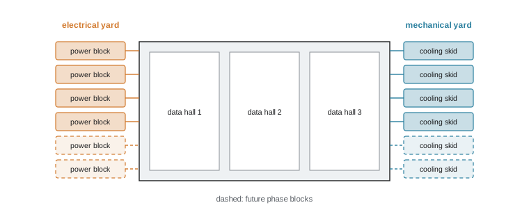
Large campuses typically combine a conventionally built or precast shell with highly prefabricated electrical and mechanical systems, which carry most of the value and complexity. Electrical "power blocks" (medium-voltage switchgear, transformers, UPS and batteries in skids or enclosures) are repeated for each increment of capacity.
Schedule benefits
The main schedule benefit comes from overlapping work that would otherwise be sequential. In conventional construction, electrical rooms are built after the structure is closed in; with prefabricated power modules, they are built in a factory during site preparation and foundations, and installed as soon as their pads are ready.
Worked problem
Schedule compression
A conventional build takes 4 months for site works and foundations, 6 months for the structure and envelope, 7 months for electrical and mechanical installation and 2 months for commissioning (19 months total, in sequence). With prefabrication, 5 of the 7 months of electrical and mechanical work move to the factory, starting at the same time as site works, and the remaining on-site work takes 3 months after the envelope is complete. Estimate the new duration.
Show solution
- Factory work: 5 months, starting at month 0, finishing at month 5, well before it is needed.
- Site sequence: site works 4 + structure 6 + on-site installation and connection 3 + commissioning 2 = 15 months.
Answer: About 15 months instead of 19, a saving of 4 months, provided factory output arrives on time. Further savings come from prefabricating the structure and envelope, and from commissioning modules in the factory so that site commissioning focuses on integration.
Transport limits
Everything built off site must travel by road, and sometimes rail or sea, to the site. Module dimensions are therefore set by transport rules:
In the US, federal and state rules set a legal width of 8.5 ft (2.6 m), height commonly 13.5 to 14 ft (4.1 to 4.3 m) depending on the state, and a gross weight of 80,000 lb (36,300 kg) on Interstates. Loads beyond these need state oversize and overweight permits for each state crossed, route surveys, escort (pilot) vehicles and travel restrictions; superloads may need engineering review of bridges and police escort.
Common module sizes are therefore about 3.6 to 4.3 m wide (permitted as oversize but routine), 3.6 to 4.3 m tall on low-bed trailers, and 12 to 18 m long. Designers check the route, including bridges, overhead wires, turns, rail crossings and the site entrance, early in design.
Worked problem
Height of a load on a trailer
A power module is 3.9 m tall. Carried on a lowboy trailer with a deck height of 0.6 m, what is the overall height? Does it fit under a 4.15 m legal limit, and what about a bridge with 4.8 m clearance?
Show solution
- Overall height: \(3.9 + 0.6 = 4.5\) m.
- Exceeds 4.15 m, so an oversize permit is needed; clears the 4.8 m bridge by 0.3 m.
Answer: The load is 4.5 m high, requiring a permit and a route avoiding structures lower than about 4.7 m (allowing a safety margin). A double-drop trailer with a lower deck, or splitting the module, could reduce the height.
Lifting and setting
Modules, skids and precast elements are placed by crane. Lift planning considers the load's weight and center of gravity, rigging (spreader bars, slings), the crane's rated capacity at the required radius (capacity falls rapidly as radius increases), ground bearing under the crane outriggers or tracks, wind limits, and exclusion zones. Critical lifts (often defined as over 75% of the crane's capacity, over occupied areas or involving multiple cranes) require engineered lift plans.
Worked problem
Crane capacity at radius
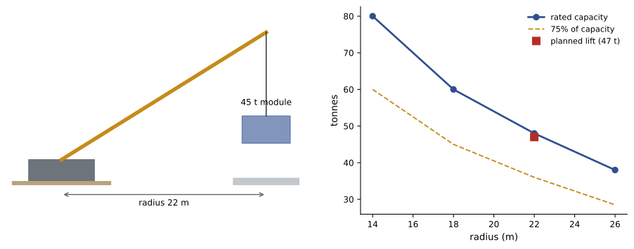
A 45-metric ton power module must be set at a radius of 22 m. A crane's load chart gives 80 t at 14 m, 60 t at 18 m, 48 t at 22 m and 38 t at 26 m (with the planned counterweight and boom). Rigging weighs 2 t. Is the lift acceptable, and is it a critical lift under a 75% rule?
Show solution
- Total load: \(45 + 2 = 47\) t; capacity at 22 m: 48 t.
- Utilization: \(47/48 = 98\%\).
Answer: The crane is at 98% of capacity, technically within its chart but far above a 75% critical-lift threshold, leaving almost no margin for errors in weight or radius. A larger crane, a closer crane position (60 t at 18 m would give 78%) or a different setting sequence is needed.
Approvals and certification
Factory-built buildings and equipment must still meet building, electrical and fire codes, but inspections are partly moved to the factory:
In the US, many states run modular (industrialized) building programs in which plans are reviewed and units inspected in the factory by the state or third-party agencies, and approved units carry a state insignia accepted by local building officials, who then inspect foundations and site connections. ICC/MBI standards 1200 and 1205 cover the design, plan review, inspection and installation of off-site construction. Electrical assemblies must be listed by a nationally recognized testing laboratory (such as UL) or receive field evaluation, and the NEC applies to their installation.
Early engagement with the authority having jurisdiction is essential, because some officials are unfamiliar with large factory-built power and data modules, and approvals can be delayed if certification routes are unclear.
Interfaces and tolerances
A prefabricated module is only as good as its fit with the site. Interfaces include anchor bolts and pads, electrical connections between modules and to the utility, piping connections, controls and monitoring networks, fire protection, and weather sealing between modules. Factories build to tight tolerances, but foundations and site work vary more, so designers specify tolerances for pad elevations and anchor locations, provide adjustable connections (slotted holes, shims, flexible pipe connectors, cable slack), and use digital tools (building information models, laser scanning of pads before setting) to verify fit.
Worked problem
Pad tolerance stack-up
A module rests on four pads. The specification allows each pad elevation to vary by ±6 mm, and the module's base frame can tolerate up to 10 mm difference between any two support points before shimming. What is the worst-case difference, and is shimming planned?
Show solution
- Worst case: one pad +6 mm and another −6 mm: 12 mm difference.
- 12 mm exceeds the 10 mm tolerance.
Answer: The worst case is 12 mm, so either the pad tolerance must be tightened (to ±5 mm or better) or shim plates must be planned. Surveying pads before modules ship allows shims to be prepared in advance.
Modularity and phasing
Modular design also means designing the facility as repeated capacity blocks that can be added as demand grows: for example, a campus planned for 300 MW built in 25 MW phases, each with its own power and cooling blocks. Benefits include matching capital spending to demand, adopting newer equipment in later phases, and reducing risk. Structural and civil design supports this by providing foundations, duct banks, roads and utility corridors for later phases (or at least space and connection points), designing expansion joints and building ends for extension, and arranging phases so construction does not disrupt operating data halls.
Worked problem
Capacity blocks
A data hall needs 24 MW of IT load with N+1 redundancy at the block level (DCE-340), using prefabricated power blocks of 3 MW each. How many blocks are needed, and if each block takes 6 weeks to set and connect with two crews working in parallel, how long does installation take?
Show solution
- Blocks for load: \(24/3 = 8\); with N+1: 9 blocks.
- Two crews: \(\lceil 9/2 \rceil = 5\) rounds × 6 weeks = 30 weeks; with overlapping crews and staggered deliveries, typically less.
Answer: Nine power blocks, installed over about 30 weeks with two crews. More crews or larger blocks shorten installation, but factory output, delivery logistics and crane availability often set the real pace.
The limits of modularity
Not everything should be prefabricated. Very large components may exceed transport limits; designs still changing rapidly (such as cooling for new generations of AI hardware) may be better built on site; and modules need enough repetition to justify factory setup. Modular buildings also have more joints and connections to seal and maintain. The best results come from a clear strategy: standardize what repeats, prefabricate what benefits from factory conditions, and leave flexibility where requirements are uncertain.
Lesson 12 places prefabrication within the overall construction sequence, quality assurance and handover of the project.
Common mistakes
MistakeDesigning modules without checking the transport route.
InsteadSurvey routes for height, width, weight, bridges and turns early.
MistakePlanning lifts near the crane's full chart capacity.
InsteadKeep utilization below critical-lift thresholds or engineer the lift.
MistakeAssuming local officials accept factory certification automatically.
InsteadAgree certification and inspection routes with the authority having jurisdiction early.
MistakeSpecifying pad tolerances looser than module tolerances.
InsteadMatch tolerances, survey pads and plan shims.
MistakePrefabricating designs that are still changing.
InsteadStandardize stable elements; keep flexibility where requirements are uncertain.
Summary and key terms
- Prefabrication shortens schedules by overlapping factory and site work and improves quality and safety.
- Forms range from components and MEP racks to skids, power modules, volumetric data halls and integrated racks.
- Federal and state limits (8.5 ft wide, about 13.5–14 ft high, 80,000 lb) drive module sizes; larger loads need permits.
- Crane capacity falls with radius; critical lifts need engineered plans.
- State modular programs and ICC/MBI 1200/1205 move inspection to the factory; electrical assemblies need listing or field evaluation.
- Interfaces and tolerances must be designed and verified between factory and site.
- Repeated capacity blocks support phased growth.
- Prefabricate what repeats and is stable; keep flexibility elsewhere.
- DfMA
- Design for manufacture and assembly.
- Factory acceptance test
- Testing equipment in the factory before shipment.
- Skid
- Equipment mounted on a common structural base for transport and installation.
- eHouse
- A prefabricated enclosure containing electrical equipment.
- Volumetric module
- A three-dimensional factory-built unit forming part of a building.
- Oversize load
- A load exceeding legal dimensions, requiring permits.
- Load chart
- A crane's rated capacity at each radius and configuration.
- Critical lift
- A lift requiring an engineered plan due to weight, location or complexity.
- Tolerance
- Permitted variation from specified dimensions.
- Capacity block
- A repeated unit of power and cooling capacity added in phases.
Practice problems
Work each problem on paper first, then reveal the answer to check.
Give three advantages and two disadvantages of prefabrication.
Show answer
Advantages: speed, quality, labor efficiency, safety, repeatability. Disadvantages: less late flexibility, transport limits, interfaces, factory capacity dependence.
Why do power modules suit prefabrication?
Show answer
They are complex, repeated, high-value and benefit from factory testing.
A 4.2 m module on a 0.5 m deck. Overall height?
Show answer
4.7 m.
A 30 t load with 1.5 t rigging, crane capacity 40 t at the radius. Utilization?
Show answer
79%: a critical lift under a 75% rule.
Why must ground bearing under outriggers be checked?
Show answer
Outrigger loads can exceed soil capacity, causing the crane to tip.
Pads at ±4 mm. Worst-case difference between two pads?
Show answer
8 mm.
18 MW load, 2.5 MW blocks, N+1. Blocks needed?
Show answer
8 for load (7.2 rounded up) plus 1 = 9.
What do state modular programs provide?
Show answer
Plan review and in-factory inspection, with an insignia accepted by local officials.
How does phasing reduce risk?
Show answer
Capital is spent as demand materializes, and later phases can adopt newer technology.
When should a component not be prefabricated?
Show answer
When it exceeds transport limits, is not repeated, or its design is still changing.
Lesson quiz · 5 questions
Score 60% or more to complete this lesson.
Create a free account to save your progress, take quizzes and earn a certificate.