
DCE-430 · Lesson 1 of 12 · 34 min
Site grading, roads and stormwater
A data center campus is a large industrial development: a hyperscale site can cover 20 to 100 hectares, with buildings hundreds of meters long, substations, generator yards, fuel storage, cooling equipment, roads for heavy deliveries and parking. Before any structure is designed, civil engineers shape the land: grading it so buildings sit on level, well-drained pads; designing roads that can carry the heaviest equipment ever delivered to the site; and managing the large volumes of rainwater that run off roofs and pavement. Mistakes here are expensive to fix later and can flood a facility whose whole purpose is reliability. This course applies civil and structural engineering (CIV-330, CIV-340) to data centers; this lesson covers the site, and the section at the end of the lesson shows how the twelve lessons fit together.
Site investigation
Civil design starts with information about the site:
- A topographic survey, typically with contours at 0.25 to 0.5 m intervals from ground survey, drone photogrammetry or lidar, plus existing utilities, trees, watercourses and boundaries.
- A geotechnical investigation: boreholes and test pits to identify soil and rock layers, groundwater levels, bearing capacity, settlement characteristics, frost susceptibility and, in seismic regions, the site class used in seismic design (Lesson 7). Investigations for large buildings typically place boreholes every 30 to 60 m across the footprint.
- Environmental and hydrological information: floodplains, wetlands, watercourses and their setbacks, contamination from previous uses (DCE-410).
- Utility capacity: water, sewer, power and fiber routes.
Data center owners increasingly standardize their building designs and adapt them to each site, so site conditions that differ from the standard, such as poor soils, high groundwater or a steep slope, must be identified early because they change foundation and grading costs significantly.
Grading
Grading reshapes the ground to provide level building pads, drain water away from buildings and toward collection systems, and give vehicles acceptable slopes. Typical criteria are:
- Building pads: level, with the finished floor elevation set above the design flood level with freeboard (often 0.3 to 0.6 m above the 100-year flood level, more for critical facilities; some owners use the 500-year level) and above surrounding grades.
- Ground sloping away from buildings at 2 to 5% for at least 3 m.
- Paved areas at 1 to 2% minimum for drainage; grassed areas at 2% minimum; slopes steeper than 3 horizontal to 1 vertical need erosion protection or retaining walls.
- Roads with longitudinal grades usually under 6 to 8% for heavy trucks, and gentler where heavy-haul equipment is delivered.
Grading design aims to balance cut and fill on site, since importing or exporting soil is costly. Unsuitable soils (organic topsoil, soft clay) must be stripped and replaced with engineered fill compacted in layers to a specified density, typically 95 to 98% of the standard or modified Proctor maximum dry density under buildings.
Worked problem
Cut and fill volume
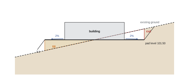
A building pad 200 m by 120 m is to be set at elevation 101.50 m. The existing ground slopes uniformly from 100.80 m on one long side to 102.20 m on the other. Estimate the cut and fill volumes, ignoring side slopes and topsoil.
Show solution
- The ground crosses 101.50 m exactly halfway across the 120 m width (it rises 1.40 m across 120 m, so 0.70 m in 60 m).
- Fill side: average depth \(0.70/2 = 0.35\) m over \(200 \times 60 = 12{,}000\) m² \(= 4200\) m³.
- Cut side: same geometry, 4200 m³.
Answer: About 4200 m³ of cut and 4200 m³ of fill, which balance. Setting the pad 0.2 m higher would add about 4800 m³ of fill (0.2 m × 24,000 m²) and remove 4800 m³ of cut, so pad elevation is a key lever on earthworks cost. In practice, fill must be engineered and compacted, and shrinkage of cut material (typically 10 to 20%) means more cut is needed than the fill volume.
Roads, access and heavy haul
Data center sites need several kinds of vehicle access:
- Heavy-haul routes for the largest deliveries: power transformers of 50 to 200 metric tons or more, generators of 30 to 60 metric tons, and prefabricated modules. These arrive on multi-axle trailers whose gross weight can exceed 300 metric tons, requiring special permits, route surveys, and roads, culverts and bridges designed for the load.
- Truck routes for routine deliveries, fuel trucks and maintenance vehicles, with turning radii for tractor-trailers (typically 15 m outside radius for a WB-20 or WB-67 design vehicle).
- Fire department access, which building codes specify (see below).
- Staff and visitor parking and secure entry, with vehicle barriers and controlled gates (DCE-440).
Pavements are designed for traffic loading over their life. Flexible (asphalt) pavements suit general roads; rigid (concrete) pavements suit truck aprons, generator yards and areas with fuel spills or heavy point loads. Pavement design converts mixed traffic into equivalent single-axle loads (ESALs) and sizes layer thicknesses for the subgrade strength. A few heavy-haul deliveries do relatively little cumulative damage, but a single overload on a weak subgrade or a buried pipe can cause failure, so heavy-haul routes are checked separately.
Worked problem
Axle loads of a transformer delivery
A 180-metric ton transformer is delivered on a trailer weighing 60 metric tons, pulled by a 25-metric ton tractor. The trailer has 12 axle lines. Estimate the load per trailer axle line, assuming the tractor carries its own weight plus 10% of the trailer and transformer.
Show solution
- Trailer and transformer: \(180 + 60 = 240\) t; 90% on the trailer axles \(= 216\) t.
- Per axle line: \(216/12 = 18\) t.
Answer: About 18 metric tons per axle line, well above the roughly 9 to 10 metric tons allowed on a normal single axle (and each axle line usually has 8 tires across the trailer width). Heavy-haul roads, culverts and buried utilities must be checked for these loads, and temporary mats or crossings are often used to protect pipes.
In the US, the International Fire Code (Section 503 and Appendix D, as adopted locally) requires fire apparatus access roads with an unobstructed width of at least 20 ft (26 ft near hydrants and for aerial apparatus access), vertical clearance of at least 13 ft 6 in, turning radii set by the fire code official, and surfaces designed to carry apparatus loads (often 75,000 lb). Dead ends longer than 150 ft need turnarounds, and access roads must reach within 150 ft of all portions of the exterior walls.
Stormwater: why it matters
Developing a site replaces soil and vegetation, which absorb much of the rain, with roofs and pavement, which shed almost all of it. Runoff peaks rise several-fold and arrive sooner, and total runoff volume increases. Without control, development causes downstream flooding, erosion of channels and pollution from sediment, oil and chemicals. Regulators therefore require new developments to manage stormwater, typically by limiting post-development peak flows to pre-development rates for a range of storms (often the 2-year to 100-year events), treating runoff to remove sediment, and in many places retaining the first part of each storm on site.
Data centers are an extreme case: their roofs and paved areas can cover 60 to 80% of the site. Stormwater facilities, such as ponds and underground tanks, can take a significant share of land and cost, and their design also protects the facility itself, since the site must stay dry in storms larger than the design event.
The rational method
For small catchments (typically under 50 to 80 ha), peak runoff is estimated with the rational method:
where \(Q\) is the peak flow in m³/s, \(C\) the dimensionless runoff coefficient (the fraction of rainfall that runs off), \(i\) the rainfall intensity in mm/h for a storm lasting the time of concentration, and \(A\) the area in hectares. (In US customary units, \(Q = CiA\) gives cubic feet per second with \(i\) in in/h and \(A\) in acres.) The time of concentration \(t_c\) is the time for runoff to travel from the most distant point to the outlet. Intensity comes from intensity-duration-frequency (IDF) curves published for each location, which give the average intensity for storms of a given duration and return period.
| Surface | Typical C |
|---|---|
| Roofs | 0.90–0.95 |
| Asphalt and concrete pavement | 0.85–0.95 |
| Gravel yards | 0.50–0.70 |
| Lawns, flat sandy soil | 0.05–0.15 |
| Lawns, clay soil | 0.15–0.35 |
| Meadow and woodland | 0.10–0.30 |
Worked problem
Peak runoff before and after development
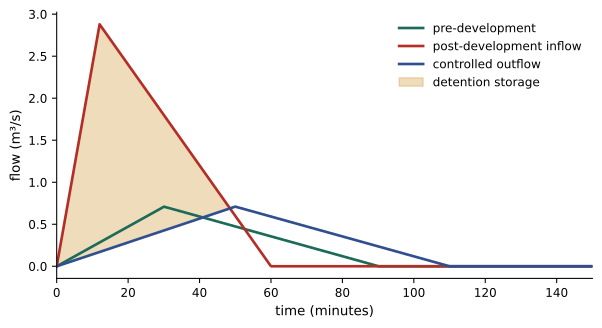
A 12 ha site of meadow (C = 0.30) is developed with 70% roofs and paving (C = 0.92) and 30% landscaping (C = 0.25). For a 100-year storm, the IDF curve gives 71 mm/h for 30 minutes (the pre-development time of concentration) and 120 mm/h for 12 minutes (post-development). Compute both peaks.
Show solution
- Post-development C: \(0.7 \times 0.92 + 0.3 \times 0.25 = 0.72\).
- Pre: \(Q = 0.30 \times 71 \times 12/360 = 0.71\) m³/s.
- Post: \(Q = 0.72 \times 120 \times 12/360 = 2.88\) m³/s.
Answer: The peak rises from 0.71 to 2.88 m³/s, about four times, both because more rain runs off and because it arrives faster. Detention must hold the difference and release it slowly.
Detention and retention
Detention facilities store runoff temporarily and release it through a controlled outlet (an orifice or weir sized so the outflow never exceeds the allowable rate). Common forms are dry ponds, wet ponds (which also settle sediment and treat water), underground chambers and tanks under parking areas, and rooftop storage. Retention and infiltration facilities (bioretention, infiltration trenches, permeable pavement) keep water on site to soak in or evaporate, reducing runoff volume and recharging groundwater; many jurisdictions now require a minimum retention volume, often the first 10 to 25 mm of each storm.
The required detention volume is the largest difference between inflow and outflow volumes over the range of storm durations. The modified rational method computes this by trying storms of increasing duration:
import numpy as np

# site: 12 ha campus, modified rational method for detention sizing
A = 12.0                       # drainage area (ha)
C_pre, C_post = 0.30, 0.72     # runoff coefficients: meadow before; 70% roofs and paving after

def intensity(t_min, a=1400.0, b=8.0, n=0.82):
    # IDF curve for a 100-year storm, i = a / (t + b)^n in mm/h (illustrative coefficients)
    return a / (t_min + b) ** n

def Q(C, i):
    return C * i * A / 360.0    # rational method, m3/s (i in mm/h, A in ha)

tc_pre, tc_post = 30.0, 12.0    # times of concentration (min)
Q_allow = Q(C_pre, intensity(tc_pre))
print(f"pre-development peak (100-yr): {Q_allow:.2f} m3/s;  post-development uncontrolled: {Q(C_post, intensity(tc_post)):.2f} m3/s")

# storage needed = max over storm durations of (inflow volume - outflow volume)
best = (0, 0)
for d in range(10, 361, 5):
    inflow = Q(C_post, intensity(d)) * d * 60
    outflow = Q_allow * d * 60 * 0.5 + Q_allow * tc_post * 60 * 0.5   # outflow rises linearly as the pond fills
    need = inflow - outflow
    if need > best[1]:
        best = (d, need)
print(f"critical storm duration {best[0]} min, detention volume about {best[1]:.0f} m3")
print(f"pond 1.5 m deep would need about {best[1] / 1.5:.0f} m2 ({best[1] / 1.5 / (A * 10000) * 100:.1f}% of the site)")pre-development peak (100-yr): 0.71 m3/s; post-development uncontrolled: 2.88 m3/s critical storm duration 50 min, detention volume about 2291 m3 pond 1.5 m deep would need about 1527 m2 (1.3% of the site)
For this campus, controlling the 100-year peak to the pre-development rate requires about 2300 m³ of storage, governed by a 50-minute storm, longer than the 12-minute time of concentration. A pond 1.5 m deep would cover about 1500 m², about 1.3% of the site, although in practice side slopes, freeboard, access and multiple design storms make ponds two to three times this area. Where land is valuable, underground tanks under paving are used, at higher cost.
Worked problem
Sizing a control orifice
A pond outlet must pass 0.71 m³/s at a maximum water depth of 1.5 m above the orifice center. With a discharge coefficient of 0.6, what orifice diameter is needed?
Show solution
- Orifice equation: \(Q = C_d A \sqrt{2gh}\).
- \(\sqrt{2 \times 9.81 \times 1.5} = 5.42\) m/s; \(A = 0.71/(0.6 \times 5.42) = 0.218\) m².
- Diameter \(= \sqrt{4A/\pi} = 0.527\) m.
Answer: About a 530 mm orifice. Real outlets usually combine a small orifice for frequent storms with larger openings or a weir higher up for the 100-year event, so that each design storm is limited to its pre-development peak, plus an emergency spillway for storms beyond the design.
Water quality and erosion control
Stormwater carries sediment, metals from roofs and vehicles, hydrocarbons and, at data centers, possible spills of diesel fuel, glycol and other fluids. Treatment measures include oil-grit separators, wet ponds and wetlands, bioretention and filter strips, and spill containment around fuel and generator areas (DCE-340), with shut-off valves to keep spills out of the storm system. During construction, when large areas of bare soil are exposed, erosion and sediment control (silt fences, sediment basins, stabilized construction entrances, staged clearing and prompt revegetation) prevents sediment from leaving the site.
In the US, the Clean Water Act requires construction sites disturbing 1 acre or more to obtain coverage under a National Pollutant Discharge Elimination System (NPDES) construction general permit, issued by the EPA or the state, and to prepare and implement a stormwater pollution prevention plan (SWPPP) with erosion and sediment controls and inspections. After construction, local stormwater ordinances and state rules (often tied to municipal separate storm sewer system, MS4, permits) set peak-flow and water-quality requirements. Industrial stormwater permits may also apply to facilities with exposed fuel storage and equipment. Work in wetlands or streams needs Section 404 permits from the US Army Corps of Engineers.
Designing beyond the code event
Regulations define the storms a stormwater system must control, but a critical facility must also survive larger events. Good practice includes overland flow routes that carry water around buildings when pipes are overwhelmed, finished floor levels well above the routes' water levels, no below-grade critical equipment without flood protection, and checking the site for extreme rainfall such as the 500-year storm or a probable maximum precipitation scenario. Rainfall intensities are increasing in many regions, so designers increasingly apply climate change factors (often 10 to 20% increases in design intensities) to IDF curves.
How this course is organized
The twelve lessons move from the site to the finished, resilient building:
- Lesson 1 (this lesson): site investigation, grading, roads and stormwater management.
- Lesson 2: site utilities: fire and cooling water, drainage, fuel, duct banks and fiber routes.
- Lesson 3: floor loads, slabs on grade and foundations.
- Lesson 4: soils, consolidation, earthworks and ground improvement.
- Lesson 5: structural systems, load combinations, roof equipment, ponding and overhead services.
- Lesson 6: steel structures and long-span roofs.
- Lesson 7: snow, wind and earthquake design under ASCE 7 and the IBC.
- Lesson 8: concrete structures: tilt-up, precast and multi-story floors.
- Lesson 9: prefabrication and modular construction.
- Lesson 10: building envelope, roofing and moisture control.
- Lesson 11: resilience: flood, extreme wind, vehicle and blast hazards.
- Lesson 12: construction, quality assurance, embodied carbon and a site design project.
Common mistakes
MistakeSetting the building pad level without a cut-fill balance study.
InsteadOptimize pad elevation to balance earthworks while meeting flood freeboard.
MistakeDesigning roads only for normal trucks.
InsteadCheck heavy-haul routes, culverts and buried utilities for transformer and module deliveries.
MistakeUsing pre-development C values for developed areas.
InsteadCompute weighted C from the actual roof, paving and landscape areas.
MistakeSizing detention for a single storm duration.
InsteadFind the critical duration that maximizes required storage.
MistakeAssuming the code storm is the worst the site will see.
InsteadProvide overland flow routes and freeboard for larger storms.
Summary and key terms
- Site design begins with topographic, geotechnical, environmental and utility investigations.
- Grading sets level pads above flood levels, drains water away and balances cut and fill.
- Roads must carry heavy-haul deliveries of transformers and modules, routine trucks and fire apparatus.
- IFC fire apparatus roads need 20 ft width (26 ft near hydrants), 13 ft 6 in clearance.
- Development raises runoff peaks and volumes; regulations limit peaks to pre-development rates.
- The rational method Q = CiA/360 estimates peaks for small catchments.
- Detention stores and releases runoff; storage is the maximum inflow-outflow difference over storm durations.
- NPDES construction permits, SWPPPs, local ordinances and Section 404 govern stormwater and erosion.
- Finished floor elevation
- The design level of a building's ground floor.
- Engineered fill
- Selected soil placed and compacted to a specified density.
- Cut and fill
- Excavation and placement of soil to reach design grades.
- Heavy haul
- Transport of exceptionally heavy loads requiring special permits and routes.
- Runoff coefficient
- The fraction of rainfall that becomes surface runoff.
- Time of concentration
- The time for runoff to travel from the farthest point to the outlet.
- IDF curve
- Intensity-duration-frequency relationship for rainfall at a location.
- Detention
- Temporary storage of runoff with controlled release.
- Retention
- Keeping runoff on site to infiltrate or evaporate.
- Hydrograph
- A plot of flow against time.
Practice problems
Work each problem on paper first, then reveal the answer to check.
Why is a geotechnical investigation needed before grading design?
Show answer
To know soil types, groundwater, bearing capacity, compaction behavior and unsuitable materials that affect pad levels and foundations.
A 100 m × 50 m pad is raised 0.3 m. Additional fill?
Show answer
1500 m³ (plus shrinkage allowance).
A 150 t transformer on a 50 t trailer with 10 axle lines carrying 90% of the load. Load per axle line?
Show answer
0.9 × 200/10 = 18 t.
Weighted C for 60% roof (0.95) and 40% lawn (0.20)?
Show answer
0.65.
Peak flow for C = 0.65, i = 90 mm/h, A = 8 ha?
Show answer
0.65 × 90 × 8/360 = 1.30 m³/s.
Why does development shorten the time of concentration?
Show answer
Smooth roofs, pavement and pipes carry water faster than soil and vegetation.
What determines the required detention volume?
Show answer
The maximum, over storm durations, of inflow volume minus allowable outflow volume.
Orifice area for 0.5 m³/s at 2.0 m head, Cd = 0.6?
Show answer
0.5/(0.6 × 6.26) = 0.133 m².
Give three stormwater quality measures for a data center.
Show answer
Oil-grit separators, wet ponds, bioretention, spill containment and shut-off valves at fuel areas.
What should protect a site in storms larger than the design event?
Show answer
Overland flow routes and finished floors above their flood levels.
Lesson quiz · 5 questions
Score 60% or more to complete this lesson.
Create a free account to save your progress, take quizzes and earn a certificate.