
CMP-350 · Lesson 2 of 12 · 24 min
Diodes in digital systems: protection, ESD and LEDs
ELE-240 Electronics I treats the diode as an analog device in rectifiers, regulators and clippers. In digital hardware diodes appear in quieter but equally important roles. Every input and output pin on a microcontroller has diodes built in to steer away dangerous voltages. Boards add transient voltage suppressors to absorb electrostatic discharge and surges. Diodes stop current flowing backwards from a battery, catch the energy of a relay coil when it switches off, and combine supplies so that a device runs from whichever source is present. Light-emitting diodes report status and, in optocouplers, carry signals across an isolation barrier. This lesson covers each of those jobs from the digital designer's point of view, with numbers from the NS-5 board.
Diode models a digital designer uses
The full diode equation from lesson 1 is rarely needed at a logic designer's desk. Three simpler models cover most cases. The ideal switch model treats the diode as a short circuit when forward biased and an open circuit when reverse biased; it is good enough for working out which way current flows. The constant-drop model adds a fixed forward voltage, about 0.7 V for a silicon junction diode at a few milliamps, 0.3 to 0.45 V for a Schottky diode, and 1.8 to 3.2 V for an LED depending on color. The third model adds a small series resistance for currents where the voltage drop rises noticeably with current. Datasheets give the forward voltage at a stated current and temperature; the drop falls by about 2 mV for every degree of temperature rise.
Schottky diodes, made from a metal-semiconductor contact rather than a pn junction, matter in digital circuits for two reasons. Their forward drop is lower, so they waste less voltage in a power path, and they switch almost instantly because they store very little charge. The price is much higher reverse leakage, which can reach microamps or more at high temperature. For the NS-5's reverse-polarity protection and supply OR-ing, that trade-off has to be weighed against the sleep-current budget written in CMP-315.
Input protection diodes on every pin
Look at the equivalent circuit in any microcontroller datasheet and each pin shows two diodes: one from the pin to the supply rail V_DD and one from ground to the pin. Normally both are reverse biased because the pin voltage stays between ground and V_DD. If something drives the pin above V_DD plus about 0.5 V, the upper diode conducts and dumps the excess current into the supply. If the pin goes below ground by about 0.5 V, the lower diode conducts from ground. These clamps protect the delicate gate oxide of the input transistor, which can be destroyed by a few volts beyond its rating.
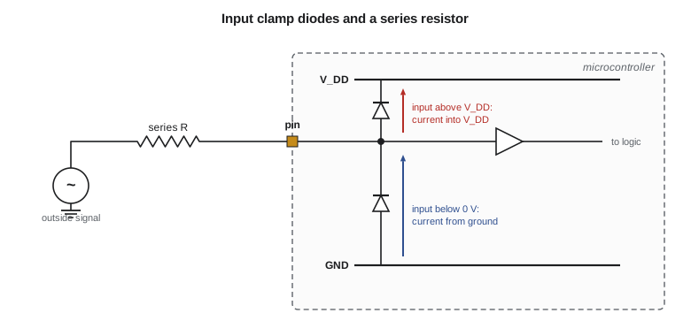
The clamps are not designed to carry continuous current. Datasheets give an injection current limit, commonly a few milliamps per pin and a total limit for the whole chip. Exceeding it can cause latch-up, in which parasitic transistors formed by the chip's wells switch on and short the supply until power is removed, sometimes destroying the part. Injected current can also corrupt nearby analog inputs. When a signal might leave the supply range, the designer adds a series resistor to keep the clamp current within the limit.
There is a subtler failure that bites battery-powered designs: back-powering. If the microcontroller's supply is switched off but a signal from another board is still high, current flows through the upper clamp diode into the unpowered V_DD rail. The chip may half-wake, other parts on the rail may draw current, and the total can drain a battery or leave the system in a strange state when power returns. Ines found exactly this on an early NS-5 prototype: the radar module stayed powered from its own supply and held its data line high while the microcontroller slept with its rail switched off, feeding about 1.4 mA backwards into the 3.3 V rail.
Worked problem
Sizing a series resistor for clamp current
A 5 V signal from the NS-5 radar module must drive a 3.3 V microcontroller input whose clamp diode conducts at about 0.5 V above V_DD. The datasheet allows 2 mA of injection current per pin. Find the smallest series resistor, and the resistor if the designer wants to stay below 0.5 mA.
Show solution
- \[ V_{\text{clamp}} = 3.3 + 0.5 = 3.8\ \text{V}\]
- \[ R_{\min} = \frac{5.0 - 3.8}{2\ \text{mA}} = 600\ \Omega\]
- \[ R_{0.5\,\text{mA}} = \frac{5.0 - 3.8}{0.5\ \text{mA}} = 2.4\ \text{k}\Omega\]
Answer: A 600 Ω resistor meets the absolute limit; 2.4 kΩ, rounded up to 2.7 kΩ, keeps the clamp current to about 0.44 mA. Lesson 10 explains why a proper level translator is usually better than relying on clamps.
Electrostatic discharge
Walking across a carpet can charge a person to 10 kV or more. When a charged finger or tool touches a connector pin, the stored charge flows in a few nanoseconds, with peak currents of several amps. Chips survive handling because their pins include ESD protection structures, usually rated by the human body model at 2 kV, but that rating covers careful assembly in a controlled factory, not a field technician with a cable in the rain. Any pin that leaves the board through a connector, such as the NS-5's RS-485 terminals, the USB service port and the external sensor input, needs board-level protection.
The usual part is a transient voltage suppressor, a diode built to break down at a defined voltage and to absorb short pulses of high current. A TVS for a 3.3 V line might start conducting at about 4 V and clamp a large pulse to 8 or 9 V for its brief duration, far less than the thousands of volts arriving. TVS arrays for data lines are made with low capacitance, a few picofarads, so they do not slow fast signals. Their effectiveness depends heavily on layout: the TVS must sit right at the connector with a short, wide path to ground, so the surge is diverted before it travels along the board. The international system-level ESD test applies 8 kV contact discharges and 15 kV air discharges to exposed parts; Ines designs the NS-5 to pass it.
| Protection part | Typical use on NS-5 | Key specification |
|---|---|---|
| On-chip clamp diodes | Every microcontroller pin | Injection current limit (a few mA) |
| Series resistor | 5 V radar data into 3.3 V input | Limits clamp current |
| Low-capacitance TVS array | USB data lines | Capacitance below about 1 pF, clamp voltage |
| TVS diode, bidirectional | RS-485 A and B lines | Standoff above the −7 to +12 V common-mode range |
| TVS diode, unidirectional | 12.8 V battery input | Standoff about 15 V, surge power rating |
| Schottky or MOSFET ideal diode | Reverse-polarity protection | Forward drop, leakage, current rating |
Reverse polarity and supply OR-ing
A technician who connects a battery backwards can destroy every chip on a board in a fraction of a second, because current flows through the clamp diodes and the regulator's internal paths. The simplest protection is a series diode in the supply line: it blocks reverse current but costs its forward drop and the power that drop wastes. At 0.5 A, a silicon diode dropping 0.8 V wastes 0.4 W; a Schottky dropping 0.4 V wastes 0.2 W. For a solar-powered node that is a meaningful slice of the energy budget.
A better approach uses a MOSFET as an ideal diode. A p-channel MOSFET placed in the positive supply line, with its gate tied to ground, turns on when the battery is connected correctly and off when it is reversed. Its on-resistance replaces the diode's drop: a 20 mΩ MOSFET at 0.5 A drops only 10 mV and wastes 5 mW. Lesson 11 returns to MOSFET switches and their body diodes. When a device can run from two sources, such as the NS-5's battery and its USB service port, two diodes or ideal-diode switches OR the supplies together so that the higher source supplies the load and neither can back-feed the other.
Worked problem
Power lost in a reverse-polarity diode
The NS-5 draws an average of 2.07 mA from its 12.8 V battery, as CMP-315 calculated, but 0.45 A for 40 ms each time the modem transmits, eight times an hour. Compare the average power wasted by a Schottky diode with a 0.35 V drop and a MOSFET with 25 mΩ on-resistance. Use the average current for the sleeping load and the burst current for the modem.
Show solution
- \[ P_{\text{Schottky,sleep}} = 0.35 \times 2.07\ \text{mA} = 0.72\ \text{mW}\]
- \[ \text{burst duty} = \frac{8 \times 0.04\ \text{s}}{3600\ \text{s}} = 8.9\times10^{-5}\]
- \[ P_{\text{Schottky,burst}} = 0.35 \times 0.45 \times 8.9\times10^{-5} = 14\ \mu\text{W}\]
- \[ P_{\text{MOSFET}} \approx (2.07\ \text{mA})^{2} \times 0.025 + 0.45^{2} \times 0.025 \times 8.9\times10^{-5} \approx 0.5\ \mu\text{W}\]
Answer: The Schottky diode wastes about 0.73 mW all the time, about 3 percent of the node's roughly 26 mW average draw, while the MOSFET wastes well under a microwatt. Ines chose the MOSFET.
Inductive kickback and flyback diodes
Relays, solenoids and motor windings are inductors, and an inductor resists any change in its current. When a transistor switching a relay coil turns off, the coil's current has nowhere to go and the voltage across the coil spikes to whatever value forces the current to stop, often tens or hundreds of volts, enough to destroy the switching transistor. CMP-240 showed the waveform. A flyback diode across the coil, pointing so that it is reverse biased in normal operation, gives the current a path to circulate and decay. The voltage across the transistor is then held to the supply plus one diode drop.
The flyback diode slows the relay's release, because the current decays through the coil's own resistance instead of stopping instantly. When a fast release matters, a Zener diode or TVS in series with the flyback diode lets the voltage rise to a controlled higher level, which speeds the decay while still protecting the transistor. The NS-5 has a small relay that switches the cabinet heater on cold nights, driven by a MOSFET with a flyback diode; lesson 11 sizes it.
Light-emitting diodes
An LED is a pn junction made from a compound semiconductor such as gallium nitride or aluminum gallium indium phosphide, chosen so that electrons and holes recombine by emitting light. The emitted color depends on the band gap: red LEDs drop about 1.8 to 2.1 V, green and blue LEDs made from indium gallium nitride drop about 2.8 to 3.3 V, and white LEDs are blue LEDs coated with a phosphor. Brightness is set by current, not voltage, so an LED always needs something to limit the current, most simply a series resistor.
When a microcontroller pin drives the LED directly, the pin's own output voltage drop must be included. A pin sinking 8 mA might pull to 0.4 V rather than 0 V, as lesson 10 explains. Datasheets also limit the total current all pins can carry, so boards with many LEDs use transistor drivers or dedicated LED driver chips. Modern high-efficiency LEDs are clearly visible at 1 to 2 mA indoors; the NS-5's status LED, which must be visible in daylight from the ground below a pole, runs at 10 mA in short blinks through a MOSFET driver and is dimmed by PWM at night, as CMP-315 described.
Inside an optocoupler, an LED shines across a transparent insulating gap onto a phototransistor or photodiode. Current in the LED turns the receiver on, so a signal crosses thousands of volts of isolation with no electrical connection. The current transfer ratio, the ratio of output current to LED current, varies widely between parts and falls as the LED ages, so a reliable design drives the LED harder than the minimum and checks the worst case. Lesson 11 uses an optocoupler on the NS-5's input from the traffic cabinet.
Computing clamp and LED currents
The program below works through the common diode calculations on the NS-5 board: the LED resistor for a direct-drive indicator, the clamp current for the radar line with and without a series resistor, and the effect of temperature on a silicon diode's forward drop.
def led_resistor(vsup, vf, vol, i_f):
    return (vsup - vf - vol) / i_f

E24 = [10, 11, 12, 13, 15, 16, 18, 20, 22, 24, 27, 30,
       33, 36, 39, 43, 47, 51, 56, 62, 68, 75, 82, 91]

def next_e24_up(r):
    decade = 1
    while r >= 100 * decade:
        decade *= 10
    for base in E24 + [100]:
        if base * decade / 10 >= r:
            return base * decade / 10
    return r

# Green indicator LED driven directly from a 3.3 V pin sinking 4 mA
r = led_resistor(3.3, 2.9, 0.15, 4e-3)
print(f"green LED at 4 mA: {r:.1f} ohm -> use {next_e24_up(r):.0f} ohm")

# Red LED, same pin
r = led_resistor(3.3, 1.9, 0.15, 4e-3)
print(f"red LED at 4 mA:   {r:.1f} ohm -> use {next_e24_up(r):.0f} ohm")

# Clamp current from a 5 V radar line into a 3.3 V input
v_clamp = 3.3 + 0.5
for rs in (0, 600, 2700):
    if rs == 0:
        print("no series resistor: clamp current limited only by the source (unsafe)")
    else:
        print(f"series {rs:5d} ohm: clamp current {(5.0 - v_clamp) / rs * 1e3:.2f} mA")

# Silicon diode drop versus temperature (about -2 mV per degree)
for t in (-40, 25, 70):
print(f"diode drop at {t:3d} C: {0.70 - 0.002 * (t - 25):.3f} V")green LED at 4 mA: 62.5 ohm -> use 62 ohm red LED at 4 mA: 312.5 ohm -> use 312 ohm no series resistor: clamp current limited only by the source (unsafe) series 600 ohm: clamp current 2.00 mA series 2700 ohm: clamp current 0.44 mA diode drop at -40 C: 0.830 V diode drop at 25 C: 0.700 V diode drop at 70 C: 0.610 V
The green LED at 4 mA needs about 63 Ω, rounded up to 68 Ω, because its forward drop leaves only a quarter of a volt across the resistor. That is a warning sign: with so little voltage margin, small changes in the forward drop or the supply change the current a lot. A green LED on a 3.3 V rail is better driven at a lower current with a larger resistor, or from a higher rail through a transistor.
Common mistakes
MistakeRelying on a microcontroller's clamp diodes to translate a 5 V signal.
InsteadClamps are protection, not translation; limit the current with a resistor or use a proper level translator.
MistakePlacing a TVS diode far from the connector it protects.
InsteadPut the TVS at the connector with a short, wide ground path so the surge is diverted before it reaches the board.
MistakeDriving an LED from a voltage source without a current limit.
InsteadLED current rises steeply with voltage; always set the current with a resistor or a driver.
MistakeLeaving a relay coil without a flyback path.
InsteadAdd a flyback diode, or a diode plus Zener for faster release, to protect the switching transistor.
MistakeIgnoring back-powering through clamp diodes when a rail is switched off.
InsteadCheck every signal that can stay high while a rail is off; add series resistance or isolation switches.
Summary and key terms
- Digital designers use ideal, constant-drop and drop-plus-resistance diode models.
- Schottky diodes have lower drop and faster switching but higher leakage.
- Every microcontroller pin has clamp diodes to the rails, with a limited injection current.
- Signals above the rail need a series resistor; unpowered rails can be back-powered through clamps.
- TVS diodes at connectors absorb ESD and surges; layout determines how well they work.
- Series diodes or MOSFET ideal diodes protect against reverse polarity; MOSFETs waste far less power.
- Flyback diodes protect switches from inductive kickback.
- LEDs need a current limit; forward voltage depends on color; optocouplers use LEDs to cross isolation.
- Clamp diode
- A diode from a pin to a supply rail that conducts when the pin leaves the supply range.
- Injection current
- Current forced into a pin through its clamp diodes.
- Latch-up
- A parasitic thyristor in a CMOS chip that shorts the supply once triggered.
- Back-powering
- Unintended powering of a switched-off rail through clamp diodes from a live signal.
- TVS diode
- A transient voltage suppressor that clamps surges and ESD to a safe voltage.
- Ideal diode
- A MOSFET circuit that conducts like a diode with very low voltage drop.
- Flyback diode
- A diode across an inductive load that gives its current a path when the switch opens.
- Current transfer ratio
- An optocoupler’s output current divided by its LED current.
Practice problems
Work each problem on paper first, then reveal the answer to check.
A blue LED with V_F = 3.0 V runs from a 5 V rail through a transistor with 0.1 V drop at 5 mA. What resistor is needed?
Show answer
(5 − 3.0 − 0.1) / 5 mA = 380 Ω; use 390 Ω.
A 12 V signal enters a 3.3 V pin with a 5 mA injection limit. What is the minimum series resistance?
Show answer
(12 − 3.8) / 5 mA = 1.64 kΩ.
Why is a Schottky diode sometimes a poor choice for a battery node that sleeps most of the time?
Show answer
Its reverse leakage, especially when hot, can be a large fraction of the sleep current.
What happens to the voltage across a relay driver transistor at turn-off with no flyback diode?
Show answer
It spikes far above the supply as the coil forces its current to keep flowing, which can break down the transistor.
Lesson quiz · 5 questions
Score 60% or more to complete this lesson.
Create a free account to save your progress, take quizzes and earn a certificate.