
CIV-370 · Lesson 12 of 12 · 22 min
Capstone: site drainage and the creek crossing
The Kestrel Bay drainage study now has all its pieces: a design storm, the runoff it produces, the 100-year flood of the creek confirmed by two methods, the normal and backwater depths in the creek, a sized ditch, a pond with a rated outlet and an emergency spillway with a stilling basin. This capstone lesson assembles them into the design check that Anika must sign. It answers the three questions posed in lesson 1, and it introduces culvert hydraulics, the one remaining tool, at the level needed to judge the crossing. CIV-440 later develops culvert, bridge and storm sewer design in full.
The design basis
A drainage report begins with a design basis that lists, before any calculation, the criteria the design must meet and their sources. Reviewers read it first, and it prevents the commonest dispute in drainage approvals: a design that is correct for criteria the reviewer did not accept. Anika's design basis contains the following.
- Approvals and standards: the City of Duluth for site stormwater, with the Minnesota Stormwater Manual for methods; the FEMA Flood Insurance Rate Map and the local floodplain administrator for work in the creek's floodplain and on the lakeshore; the road authority's drainage manual for the culvert criteria applicable to the access road.
- Rainfall: the IDF relation of lesson 7 (illustrative for this course; a real design uses the published data and states its version), the 6-hour alternating block storm for hydrographs.
- Runoff: curve numbers from soil surveys and land cover, rational coefficients from the municipal tables with frequency factors, segmental times of concentration.
- Criteria: post-development peaks no greater than pre-development peaks for the 2- to 100-year storms; minor system for the 25-year storm on site; the crossing to pass the 100-year flood without overtopping the road and with freeboard; a climate check at 850 cfs; building floors at least 1 ft above the 100-year overland flow level.
Culvert hydraulics
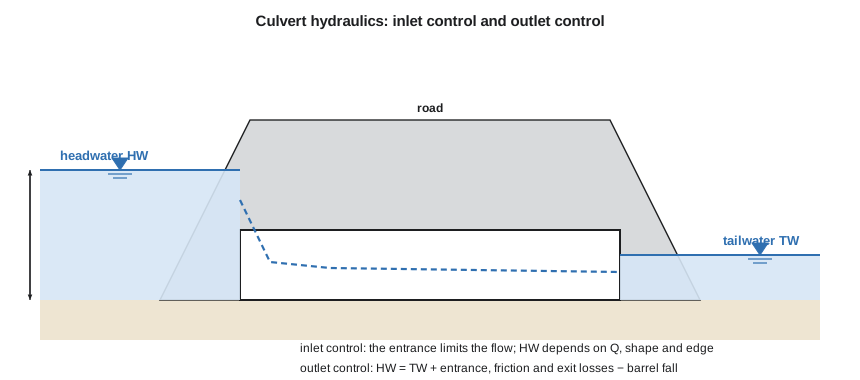
A culvert is a short conduit that carries a stream under a road or embankment. It looks simple but has two quite different ways of working, and the headwater depth, the depth of water at the entrance measured from the invert, depends on which one controls.
Under inlet control, the barrel could carry more water than the entrance lets in. The entrance acts as a weir when the headwater is low, with the flow passing through critical depth just inside, as in lesson 2, and as an orifice when the headwater submerges the top of the opening, as in lesson 6. The headwater depends only on the discharge and the geometry of the entrance: its shape, its size and the treatment of its edges. Barrel roughness, length and the tailwater have no effect. Inlet control is typical of culverts on steep slopes with low tailwater.
Under outlet control, the barrel or the tailwater limits the flow. The headwater must supply enough energy to overcome the losses at the entrance, along the barrel and at the exit, plus the tailwater level, less the fall of the barrel. For a barrel flowing full,
where \(k_e\) is the entrance loss coefficient (about 0.5 for a square-edged headwall, 0.2 for a beveled edge and 0.9 for a projecting pipe), the term in \(n\) is the Manning friction loss over the barrel length \(L\), and \(h_0\) is the larger of the tailwater depth and the average of the critical depth and the barrel height, an approximation used by the US Federal Highway Administration when the outlet is not submerged. Outlet control is typical of culverts on flat slopes with high tailwater.
Because the engineer does not know in advance which control governs, both headwaters are computed and the larger is taken. This is the procedure of the Federal Highway Administration's Hydraulic Design of Highway Culverts (HDS-5), used throughout North America. Its nomographs and the free program HY-8 give inlet control headwaters from laboratory tests of many entrance shapes. The simplified weir and orifice expressions in Sofia's script reproduce the trends but not the exact curves, and the transition between weir and orifice flow is approximate; a final design uses HY-8 or the nomographs.
Beyond hydraulics
A culvert must also be safe for road users when it overtops, stable against scour at its outlet, and passable by fish and wildlife. Outlet velocities above about 3 to 4 m/s (10 to 13 ft/s) need energy dissipation or riprap aprons, as lesson 5 discussed. Fish passage criteria, set in Canada under the federal Fisheries Act and provincial guidance and in the United States by state natural resources agencies, typically ask for barrels embedded below the stream bed with natural substrate, widths related to the bankfull width of the stream and velocities that fish can swim against. A culvert that meets the hydraulic criteria but blocks fish will not be approved, and a modern replacement is often sized as much by the stream's bankfull width as by its flood capacity.
Checking the crossing
The existing culvert is a concrete box 8 ft wide and 6 ft high, 80 ft long, on a slope of 0.004, with square-edged headwalls (\(k_e = 0.5\)) and \(n = 0.013\). The road's low point is 10.5 ft above the inlet invert. The tailwater is the creek's normal depth of 5.29 ft, since lesson 4 showed that the lake's backwater dies out long before the crossing. Anika compares it with a proposed replacement, a box 12 ft wide and 7 ft high, which is closer to the creek's bankfull width and can be embedded 1 ft with natural bed material for fish passage; the hydraulic check below uses the open height.
Worked problem
Outlet control headwater for the existing box at the 100-year flow
Compute the outlet control headwater for the 8 ft × 6 ft box at 640 cfs.
Show solution
- Full-barrel velocity and hydraulic radius:
- \[V = \frac{640}{8 \times 6} = 13.3\ \text{ft/s} \qquad R = \frac{48}{28} = 1.714\ \text{ft} \qquad \frac{V^2}{2g} = 2.76\ \text{ft}\]
- Friction loss coefficient:
- \[\frac{2(32.2)(0.013)^2(80)}{1.49^2 \times 1.714^{4/3}} = 0.191\]
- Tailwater term: \(h_0 = \max(5.29,\ (5.84 + 6.0)/2) = 5.92\) ft.
- \[HW_o = 5.92 + (1 + 0.5 + 0.191)(2.76) - 80(0.004) = 10.27\ \text{ft}\]
Answer: Outlet control alone brings the water within a few inches of the road's low point of 10.5 ft. Inlet control, with the entrance submerged and acting as an orifice, gives a higher value still, 10.67 ft, so the existing culvert overtops the road at the 100-year flow.
Sofia's script computes the inlet and outlet control headwaters for both boxes at the 100-year flow and at the climate check flow, and prints the summary of the site drainage design from the earlier lessons.
# Capstone: headwater at the Kestrel Creek crossing for the existing and a proposed box culvert
from math import sqrt
UNITS = "US"
SI = UNITS == "SI"
g, k = (9.81, 1.0) if SI else (32.2, 1.49)
L, uq = ("m", "m3/s") if SI else ("ft", "cfs")
Lb, S0, nb, ke = (24.0, 0.004, 0.013, 0.5) if SI else (80.0, 0.004, 0.013, 0.5)
crest = 3.2 if SI else 10.5             # road low point above the inlet invert
tw = 1.615 if SI else 5.286             # creek normal depth below the crossing (lesson 3)
flows = [("Q100", 18.0 if SI else 640.0), ("Q100 + 33 % (climate check)", 24.0 if SI else 850.0)]
boxes = [("existing 2.4 x 1.8", 2.4, 1.8), ("proposed 3.6 x 2.1", 3.6, 2.1)] if SI else \
        [("existing 8 x 6", 8.0, 6.0), ("proposed 12 x 7", 12.0, 7.0)]
def inlet(Q, B, D):
    q = Q / B; yc = (q * q / g) ** (1 / 3)
    if yc > D: yc = D
    Vc = Q / (B * yc)
    hw = yc + (1 + ke) * Vc ** 2 / (2 * g)          # unsubmerged: weir-like flow at the entrance
    if hw > 1.2 * D:                               # submerged: orifice flow (not below the transition depth)
        hw = max(D / 2 + (Q / (0.6 * B * D)) ** 2 / (2 * g), 1.2 * D)
    return hw, yc
def outlet(Q, B, D):
    A = B * D; P = 2 * (B + D); R = A / P; V = Q / A
    yc = min(((Q / B) ** 2 / g) ** (1 / 3), D)
    h0 = max(tw, (yc + D) / 2)
    hf = (2 * g * nb ** 2 * Lb / (k ** 2 * R ** (4 / 3))) * V * V / (2 * g)
    return h0 + (1 + ke) * V * V / (2 * g) + hf - Lb * S0, V
for name, B, D in boxes:
    print(f"{name} {L} box:")
    for fl, Q in flows:
        hi, yc = inlet(Q, B, D); ho, V = outlet(Q, B, D)
        hw = max(hi, ho); ctrl = "inlet" if hi >= ho else "outlet"
        ok = "overtops the road" if hw > crest else f"freeboard {crest - hw:.2f} {L}"
        print(f"  {fl:28s} Q = {Q:6.1f} {uq}: HW inlet {hi:.2f}, outlet {ho:.2f} -> {hw:.2f} {L} ({ctrl} control), V = {V:.2f} {L}/s, {ok}")
# site drainage summary carried forward from lessons 3, 5, 9 and 10
summary = [("ditch, 25-year", "1.85 m3/s, depth 0.58 m, shear 29 Pa" if SI else "65 cfs, depth 1.94 ft, shear 0.61 psf"),
           ("pond inflow / outflow, 100-year", "1.81 / 0.39 m3/s (pre-development 0.44)" if SI else "63.7 / 14.3 cfs (pre-development 15.1)"),
           ("pond peak stage", "1.58 m, spillway crest 1.90 m, berm 2.40 m" if SI else "5.16 ft, spillway crest 6.25 ft, berm 8.0 ft"),
           ("spillway basin", "y2 0.89 m, floor 0.67 m below creek bed" if SI else "y2 2.91 ft, floor 2.2 ft below creek bed")]
print("\nSite drainage summary")
for a, b in summary: print(f" {a:34s} {b}")existing 8 x 6 ft box: Q100 Q = 640.0 cfs: HW inlet 10.67, outlet 10.27 -> 10.67 ft (inlet control), V = 13.33 ft/s, overtops the road Q100 + 33 % (climate check) Q = 850.0 cfs: HW inlet 16.53, outlet 13.91 -> 16.53 ft (inlet control), V = 17.71 ft/s, overtops the road proposed 12 x 7 ft box: Q100 Q = 640.0 cfs: HW inlet 7.79, outlet 6.88 -> 7.79 ft (inlet control), V = 7.62 ft/s, freeboard 2.71 ft Q100 + 33 % (climate check) Q = 850.0 cfs: HW inlet 8.40, outlet 8.47 -> 8.47 ft (outlet control), V = 10.12 ft/s, freeboard 2.03 ft Site drainage summary ditch, 25-year 65 cfs, depth 1.94 ft, shear 0.61 psf pond inflow / outflow, 100-year 63.7 / 14.3 cfs (pre-development 15.1) pond peak stage 5.16 ft, spillway crest 6.25 ft, berm 8.0 ft spillway basin y2 2.91 ft, floor 2.2 ft below creek bed
Reading the results: the crossing
The existing 8 ft × 6 ft box fails. At 640 cfs it operates under inlet control with a headwater of 10.67 ft, above the 10.5 ft road low point, and its barrel velocity of 13.3 ft/s would scour the outlet. At the climate check flow of 850 cfs, the headwater would reach 16.5 ft, flooding the road deeply. The analysis also confirms the screening test of lesson 2, which showed that the box chokes the creek even without losses.
The proposed 12 ft × 7 ft box passes the 100-year flow under inlet control with a headwater of 7.79 ft, leaving 2.7 ft of freeboard to the road, and a barrel velocity of 7.6 ft/s. At the climate check flow it shifts to outlet control, with a headwater of 8.47 ft and 2.0 ft of freeboard. The new crossing therefore meets the 100-year criterion with a comfortable margin and stays open even if design floods grow by a third. Anika recommends the replacement, with beveled entrance edges to reduce the inlet loss further, the barrel embedded for fish passage, and a riprap apron at the outlet sized for the velocity.
Raising the headwater upstream of a crossing can flood neighboring land, so the change in upstream water levels between the existing and proposed culverts must also be reported. Here the replacement lowers the 100-year headwater by about 3 ft, which benefits the land upstream, but the approving agency will still want the comparison, normally from a HEC-RAS model of the reach with both structures.
Reading the results: the site
The site drainage meets its criteria. The perimeter ditch, 3 ft wide with 3H:1V sides, carries the 25-year flow of 65 cfs at 1.94 ft depth with a bed shear of 0.61 psf, well within the capacity of good grass. The pond receives a 100-year inflow of 63.7 cfs and releases 14.3 cfs, below the pre-development 15.1 cfs, rising to 5.16 ft against a spillway crest at 6.25 ft and a berm at 8.0 ft. The emergency spillway passes the full inflow if the outlet is blocked, and its stilling basin floor is set 2.2 ft below the creek bed to hold the jump at low tailwater.
Lesson 4 left one question: the high lake level raises the creek to 6.01 ft above its bed at the pond outfall. The pond bottom, and so the orifice invert, is 8.2 ft above the creek bed at the outfall, so even in the coincident flood the backwater stays about 2.2 ft below the orifice, and the outlet discharges freely; only the outlet pipe's last few feet are submerged. Dr. Kowalczyk adds two geotechnical notes to the report: the pond berm on the sand over varved clay needs the slope stability and seepage checks of CIV-440, and the empty spillway basin must be checked for uplift from the high groundwater, as the pump station was in CIV-341.
Writing the drainage report
The report that goes to the approving agencies has a predictable structure, and following it makes review faster. It contains the design basis; a description of the site, the watershed and the existing drainage; the hydrology, with the methods, inputs and results for each catchment and return period; the hydraulics of each structure, with water levels and velocities; the climate sensitivity check; drawings showing the drainage areas, the flow paths, the ditch sections, the pond grading and the outlet and culvert details; and an operation and maintenance plan. The maintenance plan matters more than it seems: orifices clog, ponds fill with sediment, grass ditches are mowed too short or not at all, and culvert entrances collect debris. A drainage system that is not maintained does not perform as designed.
Every number in the report should be traceable to an input and a method that a reviewer can check. Anika attaches Sofia's scripts, the HEC-HMS and HEC-RAS models used for the final design and a table comparing the hand calculations with the model results, which agree within a few percent.
Looking ahead
The methods of this course carry directly into later courses. CIV-380 applies hydraulics to water and wastewater treatment, from flow measurement in flumes to mixing in hydraulic jumps. The water resources design course that follows extends the hydrology and hydraulics here to reservoirs, storm sewer systems, culvert and bridge design, river engineering and adaptation to climate change. And every site design in practice, from a house lot to a highway, begins with the questions this course has answered for Kestrel Bay: where the water comes from, how much of it, how fast, and where it goes.
Practical points
- Write the design basis first and agree it with the reviewers.
- Compute both inlet and outlet control headwaters for every culvert and take the larger.
- Check velocity, scour, fish passage and upstream flooding as well as headwater.
- Test the design with a climate sensitivity check and with blocked outlets.
- Provide an operation and maintenance plan; drainage systems fail without it.
Common mistakes
MistakeComputing only outlet control for a culvert.
InsteadInlet control often governs on moderate and steep slopes; compute both.
MistakeSizing a replacement culvert only for capacity.
InsteadFish passage, scour and upstream water levels are also approval criteria.
MistakeUsing the lake level as the culvert tailwater without checking the backwater.
InsteadCompute the profile; at Kestrel Bay the backwater dies out below the crossing.
MistakeSubmitting calculations without a stated design basis.
InsteadState criteria, methods and data sources first.
Summary and key terms
- A drainage design starts with a design basis of approvals, data, methods and criteria.
- Culverts operate under inlet control (entrance limits flow) or outlet control (barrel and tailwater limit flow); the larger headwater governs.
- Outlet control: \(HW = h_0 + (1 + k_e + 2gn^2L/(k^2R^{4/3}))V^2/2g - LS_0\).
- Existing 8 × 6 ft box: HW 10.67 ft at 640 cfs, overtops. Proposed 12 × 7 ft box: HW 7.79 ft (2.7 ft freeboard); 8.47 ft at 850 cfs.
- Site: ditch 65 cfs at 1.94 ft; pond 63.7 → 14.3 cfs at 5.16 ft; spillway basin floor 2.2 ft below bed.
- Culverts must also pass fish, resist scour and not raise upstream flooding unacceptably.
- Culvert
- A short conduit carrying a stream under a road or embankment.
- Headwater
- The depth of water at a culvert entrance, measured from the inlet invert.
- Inlet control
- A culvert condition in which the entrance geometry limits the discharge.
- Outlet control
- A culvert condition in which barrel losses and tailwater limit the discharge.
- Entrance loss coefficient
- The fraction of the barrel velocity head lost at a culvert entrance.
- Design basis
- The statement of criteria, data and methods on which a design is based.
- Fish passage
- The ability of fish to move through a structure such as a culvert.
Practice problems
Work each problem on paper first, then reveal the answer to check.
A culvert barrel 5 ft × 5 ft carries 280 cfs. Find the full-barrel velocity head.
Show answer
\(V = 11.2\) ft/s, \(V^2/2g = 1.95\) ft.
For that barrel with \(k_e = 0.5\), a friction coefficient of 0.20, a tailwater term of 1.4 m (4.6 ft) and a barrel fall of 0.1 m (0.3 ft), find the outlet control headwater.
Show answer
\(4.6 + 1.70(1.95) - 0.3 = 7.6\) ft.
Changing a projecting pipe entrance (\(k_e = 0.9\)) to a beveled headwall (\(k_e = 0.2\)) changes the outlet control headwater by how much, for a velocity head of 1.0 (in the same units)?
Show answer
It lowers it by 0.7.
Why might a replacement culvert be larger than flood capacity alone requires?
Show answer
To span the stream's bankfull width with an embedded natural bed for fish passage, and to reduce scour and upstream flooding.
Lesson quiz · 5 questions
Score 60% or more to complete this lesson.
Create a free account to save your progress, take quizzes and earn a certificate.