
CIV-321 · Lesson 9 of 12 · 21 min
Matrix stiffness method I: trusses
Slope-deflection and moment distribution are displacement methods written for hand calculation. The matrix stiffness method is the same idea written for a computer. It describes each member by a small stiffness matrix, assembles those matrices into one large matrix for the whole structure, and solves \(\mathbf{K}\mathbf{D} = \mathbf{P}\) for the joint displacements. Every general-purpose structural analysis program works this way. Understanding it lets you set up models sensibly, recognize when the output cannot be right, and write small programs of your own. This lesson develops the method for plane trusses, where each member has only axial stiffness; lessons 10 and 11 extend it to beams and frames.
Degrees of freedom and the global system
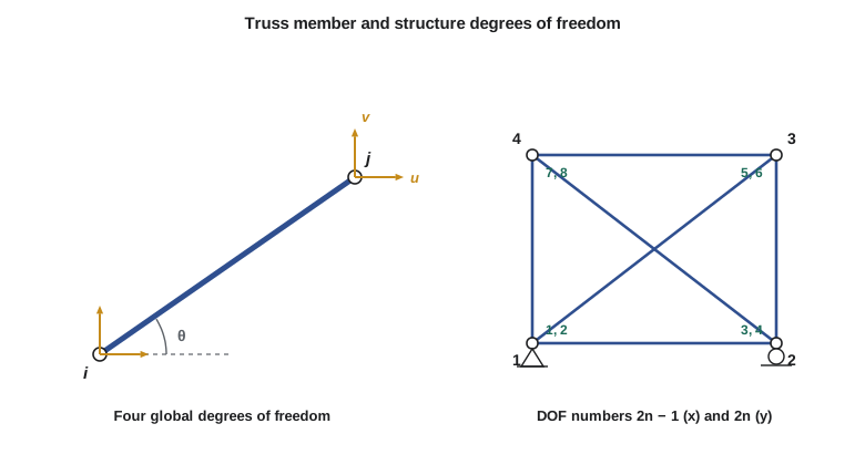
Each joint of a plane truss can move in two directions, x and y, so a truss with j joints has 2j degrees of freedom. Number them systematically: joint n has degrees of freedom \(2n - 1\) (x) and \(2n\) (y) if the joints are numbered from 1. Some of these are restrained by supports; the rest are free. The unknowns of the analysis are the displacements at the free degrees of freedom. The equations are the equilibrium of every joint in every direction:
where \(\mathbf{D}\) lists the joint displacements, \(\mathbf{P}\) the external joint forces (loads at free degrees of freedom, reactions at restrained ones), and \(\mathbf{K}\) is the structure stiffness matrix. Column j of \(\mathbf{K}\) is the set of joint forces needed to hold the structure in a deformed shape with a unit displacement at degree of freedom j and zero displacement everywhere else. This is the same idea as the unit-unknown columns built by the frame program in lesson 6.
The member stiffness matrix
In its own local axis, along the member, a truss member is a spring of stiffness \(AE/L\). If its ends move \(u_i'\) and \(u_j'\) along the axis, the end forces are
Global displacements at the ends are related to the axial ones by the direction cosines \(c = \cos\theta = (x_j - x_i)/L\) and \(s = \sin\theta = (y_j - y_i)/L\): \(u' = c\,u_x + s\,u_y\). Writing this as a transformation and applying it to both displacements and forces gives the member stiffness matrix in global coordinates:
Its rows and columns correspond to the four global degrees of freedom of the member: x and y at node i, then x and y at node j. The matrix is symmetric, and it is singular, because a member on its own can move as a rigid body without resistance. Once the end displacements are known, the axial force (tension positive) is
Assembly
The structure stiffness matrix is the sum of the member matrices, each placed into the rows and columns of its own global degrees of freedom. This is the direct stiffness method. A member from node 2 to node 4 has code numbers 3, 4, 7, 8; its 4 × 4 matrix is added into rows and columns 3, 4, 7 and 8 of the global matrix. Physically, assembly enforces two conditions at once: compatibility (members meeting at a joint share its displacements) and equilibrium (the joint forces are the sums of the member end forces).
After assembly the degrees of freedom are partitioned into free (f) and restrained (s). With the support displacements zero,
The first set of equations is solved for the unknown displacements; the second gives the reactions directly. Support settlements are handled by setting the known values in \(\mathbf{D}_s\) and moving \(\mathbf{K}_{fs}\mathbf{D}_s\) to the right-hand side, and temperature or lack of fit by adding equivalent joint forces, so the self-straining effects of lesson 4 need no special treatment.
| Property of K | Reason | Practical meaning |
|---|---|---|
| Symmetric | Maxwell's reciprocal theorem | Only half need be stored |
| Singular before supports | The free structure can move as a rigid body | Supports must be added before solving |
| Positive definite after supports (stable structure) | Any displacement stores strain energy | Gaussian elimination needs no special pivoting |
| Banded and sparse | Each joint connects to few others | Good node numbering reduces solution effort |
| Zero or tiny pivot | A mechanism or near-mechanism | The program flags instability |
A wall-mounted hoist bracket
Worked problem
Three-bar bracket by the stiffness method
A hoist bracket in the garage is a node at (16, 12) ft connected to three wall anchors at (0, 0), (0, 12) and (0, 24) ft by steel bars with \(AE = 20\,000\) kips. The hoist applies 11.0 kips downward and 4.5 kips horizontally away from the wall. Find the displacements of the node and the bar forces.
Show solution
- The bracket is indeterminate (three bars, two equations at the node), but the stiffness method does not care: there are only two free degrees of freedom, \(u\) and \(v\) at the node.
- Bars from the wall to the node: bar 1 from (0, 0), \(L = 20\) ft, \(c = 0.8\), \(s = 0.6\), \(AE/L = 1000\) kips/ft; bar 2 from (0, 12), \(L = 16\) ft, \(c = 1\), \(s = 0\), \(AE/L = 1250\) kips/ft; bar 3 from (0, 24), \(L = 20\) ft, \(c = 0.8\), \(s = -0.6\).
- Only the node-end block (the lower right 2 × 2 of each member matrix) contributes to \(\mathbf{K}_{ff}\):
- \[\mathbf{K}_{ff} = 1000\begin{bmatrix} 0.64 & 0.48 \\ 0.48 & 0.36 \end{bmatrix} + 1250\begin{bmatrix} 1 & 0 \\ 0 & 0 \end{bmatrix} + 1000\begin{bmatrix} 0.64 & -0.48 \\ -0.48 & 0.36 \end{bmatrix} = \begin{bmatrix} 2530 & 0 \\ 0 & 720 \end{bmatrix}\]
- \[u = \frac{4.5}{2530} = 0.00178\ \text{ft} = 0.021\ \text{in.} \qquad v = \frac{-11.0}{720} = -0.01528\ \text{ft} = -0.183\ \text{in.}\]
- Bar forces from \(N = (AE/L)(c\,u + s\,v)\), since the wall ends do not move:
- \[N_1 = 1000\big(0.8(0.00178) + 0.6(-0.01528)\big) = -7.74\ \text{kips} \qquad N_2 = 1250(0.00178) = 2.22\ \text{kips} \qquad N_3 = 1000\big(0.8(0.00178) - 0.6(-0.01528)\big) = 10.59\ \text{kips}\]
Answer: The lower bar is in compression (7.74 kips), the upper bar in tension (10.59 kips) and the horizontal bar takes 2.22 kips of tension. Check at the node: horizontal components \(-(0.8(-7.74) + 2.22 + 0.8(10.59)) + 4.5 = 0\) and vertical components \(-(0.6(-7.74) - 0.6(10.59)) - 11.0 = 0\). Both balance, as they must.
Consider what did not happen. We never chose a redundant, never wrote a compatibility equation and never computed a virtual work sum. Compatibility was built in when all three bars were given the same node displacement, and the solution came from two equilibrium equations. The force method would have needed one redundant and a flexibility coefficient; for this structure the two methods are equally easy, but for larger ones the stiffness method wins because it is automatic.
The procedure
- Number the joints and degrees of freedom; list the supports.
- For each member, compute L, c and s, form \(\mathbf{k}\), and add it into \(\mathbf{K}\) using its code numbers.
- Form the load vector \(\mathbf{P}_f\) from the joint loads (member loads on trusses are first converted to joint loads).
- Solve \(\mathbf{K}_{ff}\mathbf{D}_f = \mathbf{P}_f\) by Gaussian elimination.
- Compute reactions from \(\mathbf{R} = \mathbf{K}_{sf}\mathbf{D}_f\) and member forces from the end displacements.
- Check: reactions balance the loads, and every joint is in equilibrium.
Solving it in code
The program below analyses the X-braced wall bay of lesson 3 by the stiffness method. Nodes 1 to 4 here are joints 0 to 3 of lesson 3. The six member matrices are assembled into an 8 × 8 matrix, the three restrained degrees of freedom are removed, and the remaining 5 × 5 system is solved by Gaussian elimination with partial pivoting written out in plain Python.
# Matrix stiffness analysis of the X-braced wall bay (plane truss)
import math
nodes = {1: (0.0, 0.0), 2: (20.0, 0.0), 3: (20.0, 15.0), 4: (0.0, 15.0)}   # ft
AE = 22000.0                                                          # kips, all members
members = [(1, 2), (2, 3), (3, 4), (4, 1), (1, 3), (2, 4)]
restrained = {(1, 'x'), (1, 'y'), (2, 'y')}                            # pin at 1, roller at 2
loads = {(4, 'x'): 13.5}                                              # kips at node 4

dof = {}
for n in nodes:
    for d in ('x', 'y'):
        dof[(n, d)] = len(dof)
N = len(dof)
K = [[0.0] * N for _ in range(N)]
geom = []
for i, j in members:
    (xi, yi), (xj, yj) = nodes[i], nodes[j]
    L = math.hypot(xj - xi, yj - yi); c, s = (xj - xi) / L, (yj - yi) / L
    idx = [dof[(i, 'x')], dof[(i, 'y')], dof[(j, 'x')], dof[(j, 'y')]]
    t = [-c, -s, c, s]
    for a in range(4):
        for b in range(4):
            K[idx[a]][idx[b]] += AE / L * t[a] * t[b]
    geom.append((L, c, s, idx))

free = [k for k in dof if k not in restrained]
f = [dof[k] for k in free]
A = [[K[r][c] for c in f] for r in f]
b = [loads.get(k, 0.0) for k in free]
n = len(f)
for col in range(n):                                   # Gaussian elimination
    piv = max(range(col, n), key=lambda r: abs(A[r][col]))
    A[col], A[piv] = A[piv], A[col]; b[col], b[piv] = b[piv], b[col]
    for r in range(col + 1, n):
        m = A[r][col] / A[col][col]
        for c in range(col, n): A[r][c] -= m * A[col][c]
        b[r] -= m * b[col]
x = [0.0] * n
for r in range(n - 1, -1, -1):
    x[r] = (b[r] - sum(A[r][c] * x[c] for c in range(r + 1, n))) / A[r][r]
U = [0.0] * N
for k, v in zip(f, x): U[k] = v

print("node displacements (in.):")
for nd in nodes:
    print(f"  {nd}: ux = {U[dof[(nd,'x')]]*12:7.4f}  uy = {U[dof[(nd,'y')]]*12:7.4f}")
print("member forces (kips, tension +):")
for (i, j), (L, c, s, idx) in zip(members, geom):
    Nf = AE / L * (c * (U[idx[2]] - U[idx[0]]) + s * (U[idx[3]] - U[idx[1]]))
    print(f"  {i}-{j}: {Nf:7.2f}")
R = [sum(K[r][c] * U[c] for c in range(N)) for r in range(N)]
print("reactions (kips):")
for k in sorted(restrained):
print(f" node {k[0]} {k[1]}: {R[dof[k]]:7.2f}")node displacements (in.): 1: ux = 0.0000 uy = 0.0000 2: ux = 0.0736 uy = 0.0000 3: ux = 0.1749 uy = -0.0414 4: ux = 0.2485 uy = 0.0414 member forces (kips, tension +): 1-2: 6.75 2-3: -5.06 3-4: -6.75 4-1: 5.06 1-3: 8.44 2-4: -8.44 reactions (kips): node 1 x: -13.50 node 1 y: -10.13 node 2 y: 10.13
The member forces are exactly those found by the force method in lesson 3: 8.44 kips in each diagonal, 6.75 kips in the chords and 5.06 kips in the columns. The reactions balance the 13.5 kip wind load. The displacements, which the force method did not give directly, show a horizontal sway of 0.25 in. at the loaded node, or about \(h/720\).
Try deleting member (2, 4) from the list: the truss becomes determinate and the program still works, giving the tension-only result of lesson 3. Then delete member (1, 3) as well: the bay is now a mechanism, the stiffness matrix becomes singular, and the elimination meets a zero pivot. Recognizing that symptom in commercial software (often reported as an instability or a singular matrix at a named joint) is a skill worth having.
Common mistakes
MistakeComputing c and s from the wrong end of the member.
InsteadTake \(c = (x_j - x_i)/L\) and \(s = (y_j - y_i)/L\) with i the start node; use the same order when assigning code numbers.
MistakeSolving the full K before removing the restrained degrees of freedom.
InsteadThe unsupported K is singular; partition first and solve \(\mathbf{K}_{ff}\mathbf{D}_f = \mathbf{P}_f\).
MistakeUsing member forces as loads in P.
InsteadP contains external joint loads only; member forces are outputs.
MistakeIgnoring a warning about a singular matrix.
InsteadA zero or tiny pivot means the model is a mechanism: a missing member, support or connection.
Summary and key terms
- Unknowns are joint displacements; equations are joint equilibrium, \(\mathbf{K}\mathbf{D} = \mathbf{P}\).
- Truss member: \(\mathbf{k} = (AE/L)\) times the 4 × 4 matrix of \(c^2\), \(cs\), \(s^2\) terms.
- Assemble by code numbers; partition into free and restrained degrees of freedom.
- Solve \(\mathbf{K}_{ff}\mathbf{D}_f = \mathbf{P}_f\); reactions \(\mathbf{R} = \mathbf{K}_{sf}\mathbf{D}_f\); bar forces from end displacements.
- K is symmetric, banded and singular until enough supports are added.
- Degree of freedom
- An independent component of joint displacement.
- Structure stiffness matrix
- The matrix relating joint forces to joint displacements for the whole structure.
- Member stiffness matrix
- The matrix relating end forces to end displacements for one member.
- Direction cosines
- The cosine and sine of the angle a member makes with the global x axis.
- Code numbers
- The global degree of freedom numbers attached to the ends of a member.
- Direct stiffness method
- Assembly of the structure stiffness matrix by adding member matrices at their code numbers.
- Singular matrix
- A matrix with no inverse; for a structure, a sign of instability.
Practice problems
Work each problem on paper first, then reveal the answer to check.
How many degrees of freedom does a plane truss with 7 joints have, and how many are free if it has a pin and a roller?
Show answer
14 in total; 11 free.
What is the member stiffness matrix of a vertical member (\(\theta = 90^\circ\))?
Show answer
\(c = 0\), \(s = 1\): only the y terms are non-zero, \((AE/L)\) times [[0, 0, 0, 0], [0, 1, 0, -1], [0, 0, 0, 0], [0, -1, 0, 1]].
Why is the stiffness matrix of an unsupported structure singular?
Show answer
It can move as a rigid body with no force, so some non-zero displacement vectors give zero forces.
In the bracket example, what vertical deflection would a load of 22 kips downward alone produce?
Show answer
\(22/720 = 0.0306\) ft, or 0.367 in.
How are reactions obtained once the displacements are known?
Show answer
From the restrained rows of the assembled matrix, \(\mathbf{R} = \mathbf{K}_{sf}\mathbf{D}_f\).
What happens in the program if both diagonals of the X-bay are removed?
Show answer
The bay becomes a mechanism; the stiffness matrix is singular and elimination meets a zero pivot.
Lesson quiz · 5 questions
Score 60% or more to complete this lesson.
Create a free account to save your progress, take quizzes and earn a certificate.