
CIV-321 · Lesson 11 of 12 · 23 min
Matrix stiffness method III: plane frames and assembly
A frame member both stretches and bends, and its members point in different directions. Combining the truss element of lesson 9 with the beam element of lesson 10 gives a six-degree-of-freedom frame element; a rotation matrix turns it to any orientation. With that element, the assembly and solution steps you already know analyze any plane frame: the garage portals, the office wing frame, a gable roof or a braced bay with rigid joints. This lesson builds the element, assembles a frame by hand at one joint to see how the pieces fit, and then uses a complete pure-Python frame program to check the hand and approximate results of earlier lessons.
The frame element in local coordinates
In its local axes (x' along the member from node i to node j, y' perpendicular to it) a frame element has three degrees of freedom per node: axial displacement \(u'\), transverse displacement \(v'\) and rotation \(\theta\). Axial and bending behavior are uncoupled in a straight linear member, so the 6 × 6 local matrix is the truss terms and the beam terms placed side by side:
The axial stiffness \(EA/L\) is typically hundreds of times larger than the bending terms. That is why hand methods could treat members as inextensible, and why including axial deformation in a computer model changes frame moments only slightly.
Transformation to global axes
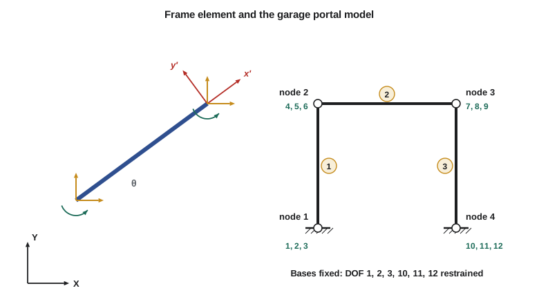
At each node the local translations are the global ones rotated by the member angle \(\theta\). With \(c = \cos\theta\) and \(s = \sin\theta\),
Placing this 3 × 3 block twice on the diagonal of a 6 × 6 matrix gives the element transformation matrix \(\mathbf{T}\), so that \(\mathbf{d}' = \mathbf{T}\mathbf{d}\). Because \(\mathbf{T}\) is a pure rotation, its inverse is its transpose. The work done by the end forces is the same in either set of axes, which leads to the global element matrix and the force transformations
Member loads are handled in local axes: the fixed-end forces \(\mathbf{q}_F'\) of lesson 10 are computed in the member's own axes, transformed to global axes with \(\mathbf{T}^T\), and subtracted from the joint load vector. After the solution, each element's end forces are recovered in local axes, where they mean axial force, shear and moment, which is what design needs.
Assembly at a joint
Worked problem
The stiffness at corner B of the garage frame
The garage end frame of lesson 6 has columns 20 ft high with \(EI = 100\,000\ \text{kip·ft}^2\) and \(EA = 449\,500\) kips, and a beam 60 ft long with \(EI = 200\,000\ \text{kip·ft}^2\) and \(EA = 562\,600\) kips. Assemble the 3 × 3 block of the structure stiffness matrix for the free degrees of freedom at corner B.
Show solution
- Column AB runs from A up to B: \(\theta = 90^\circ\), \(c = 0\), \(s = 1\). At its j end, local \(u' = v\) (along the column) and \(v' = -u\).
- Column terms at B: bending \(12EI/h^3 = 150\) kips/ft in global u; axial \(EA/h = 22\,475\) kips/ft in global v; coupling \(6EI/h^2 = 1500\) kips between u and \(\theta\); \(4EI/h = 20\,000\) kip·ft in \(\theta\).
- Beam BC runs from B to C: \(\theta = 0\), so its i-end terms go straight in: axial \(EA/L = 9377\) kips/ft in u; bending \(12EI/L^3 = 11.1\) kips/ft in v; coupling \(6EI/L^2 = 333\) kips between v and \(\theta\); \(4EI/L = 13\,333\) kip·ft in \(\theta\).
- Adding the two contributions:
- \[\mathbf{K}_{BB} = \begin{bmatrix} 9527 & 0 & 1500 \\ 0 & 22\,486 & 333 \\ 1500 & 333 & 33\,333 \end{bmatrix} \quad \text{for } \begin{bmatrix} u_B & v_B & \theta_B \end{bmatrix}\]
Answer: The horizontal stiffness at B is dominated by the beam's axial stiffness (9377 of 9527 kips/ft): the beam acts as a strut that makes the two corners sway together, which is exactly the inextensible-beam assumption of lesson 6. The off-diagonal blocks linking B to C contain the matching beam terms with negative signs, and the column contributes to the rows of the restrained base A, from which the base reactions are recovered.
The full garage frame has four nodes and twelve degrees of freedom; the two fixed bases restrain six, leaving a 6 × 6 system. Hand slope-deflection solved the same frame with three unknowns because it assumed inextensible members, which removes the two vertical displacements and ties the horizontal ones together. The computer prefers the larger but systematic system.
Building a frame model
The steps of a frame analysis are those of lessons 9 and 10, with the transformation added:
- Define nodes at joints, supports, changes of section and load points. Number them to keep the matrix bandwidth small, row by row across the frame.
- Define elements by their end nodes and section properties E, A and I. Give member loads in local or global terms consistently.
- For each element, compute L, c, s, \(\mathbf{k}'\), \(\mathbf{T}\) and \(\mathbf{k} = \mathbf{T}^T\mathbf{k}'\mathbf{T}\); add \(\mathbf{k}\) into \(\mathbf{K}\) and \(-\mathbf{T}^T\mathbf{q}_F'\) into \(\mathbf{P}\).
- Add nodal loads; apply supports (and any settlements or springs).
- Solve \(\mathbf{K}_{ff}\mathbf{D}_f = \mathbf{P}_f\); recover reactions and local end forces.
- Check equilibrium of reactions against loads, and compare key moments with a hand or approximate estimate.
Solving it in code
The program below is a general plane-frame stiffness solver in about eighty lines of plain Python. Model 1 is the garage end frame under wind and roof load together. Model 2 is the two-bay, two-level office wing frame of lesson 8 with fixed bases and the same wind loads, so its results can be set beside the portal method.
# Matrix stiffness analysis of plane frames (3 DOF per node: u, v, rotation counterclockwise)
import math

def gauss(A, b):
    n = len(b); M = [row[:] + [b[i]] for i, row in enumerate(A)]
    for c in range(n):
        p = max(range(c, n), key=lambda r: abs(M[r][c]))
        if abs(M[p][c]) < 1e-9: raise ValueError("singular stiffness matrix: the model is unstable")
        M[c], M[p] = M[p], M[c]
        for r in range(c + 1, n):
            f = M[r][c] / M[c][c]
            for k in range(c, n + 1): M[r][k] -= f * M[c][k]
    x = [0.0] * n
    for r in range(n - 1, -1, -1):
        x[r] = (M[r][n] - sum(M[r][k] * x[k] for k in range(r + 1, n))) / M[r][r]
    return x

def local_k(E, A, I, L):
    a, b, c, d, e = E * A / L, 12 * E * I / L ** 3, 6 * E * I / L ** 2, 4 * E * I / L, 2 * E * I / L
    return [[a, 0, 0, -a, 0, 0], [0, b, c, 0, -b, c], [0, c, d, 0, -c, e],
            [-a, 0, 0, a, 0, 0], [0, -b, -c, 0, b, -c], [0, c, e, 0, -c, d]]

def transform(cs, sn):                     # local = T * global
    T = [[0.0] * 6 for _ in range(6)]
    for o in (0, 3):
        T[o][o], T[o][o + 1], T[o + 1][o], T[o + 1][o + 1], T[o + 2][o + 2] = cs, sn, -sn, cs, 1.0
    return T

def matmul(A, B):
    return [[sum(A[i][k] * B[k][j] for k in range(len(B))) for j in range(len(B[0]))] for i in range(len(A))]

def transpose(A):
    return [list(r) for r in zip(*A)]

def solve_model(nodes, elems, supports, loads):
    """elems: (i, j, E, A, I, w) with w a uniform load per unit length acting in -local y"""
    n = 3 * len(nodes); K = [[0.0] * n for _ in range(n)]; P = [0.0] * n
    for (nd, d), val in loads: P[3 * nd + d] += val
    data = []
    for i, j, E, A, I, w in elems:
        (xi, yi), (xj, yj) = nodes[i], nodes[j]
        L = math.hypot(xj - xi, yj - yi); T = transform((xj - xi) / L, (yj - yi) / L)
        kl = local_k(E, A, I, L); kg = matmul(transpose(T), matmul(kl, T))
        qF = [0.0, w * L / 2, w * L * L / 12, 0.0, w * L / 2, -w * L * L / 12]   # local fixed-end forces
        fg = [sum(T[r][c] * qF[r] for r in range(6)) for c in range(6)]        # to global: T^t qF
        dofs = [3 * i, 3 * i + 1, 3 * i + 2, 3 * j, 3 * j + 1, 3 * j + 2]
        for r in range(6):
            P[dofs[r]] -= fg[r]
            for c in range(6): K[dofs[r]][dofs[c]] += kg[r][c]
        data.append((T, kl, qF, dofs))
    fixed = [3 * nd + d for nd, ds in supports for d in ds]
    free = [d for d in range(n) if d not in fixed]
    D = [0.0] * n
    for d, v in zip(free, gauss([[K[r][c] for c in free] for r in free], [P[r] for r in free])): D[d] = v
    ends = []
    for T, kl, qF, dofs in data:
        dl = [sum(T[r][c] * D[dofs[c]] for c in range(6)) for r in range(6)]
        ends.append([sum(kl[r][c] * dl[c] for c in range(6)) + qF[r] for r in range(6)])
    return D, ends

z = lambda v: round(v, 2) + 0.0
E = 29000.0 * 144                          # kip/ft^2
# Model 1: garage end frame of lesson 6 (fixed bases), wind 6.75 kips plus roof load 0.82 kip/ft
nodes = [(0, 0), (0, 20), (60, 20), (60, 0)]
col, beam = (E, 15.5 / 144, 1.0e5 / E), (E, 19.4 / 144, 2.0e5 / E)   # (E, A ft^2, I ft^4): column EI = 100 000 kip*ft^2
elems = [(0, 1) + col + (0.0,), (1, 2) + beam + (0.82,), (3, 2) + col + (0.0,)]
D, ends = solve_model(nodes, elems, [(0, (0, 1, 2)), (3, (0, 1, 2))], [((1, 0), 6.75)])
print("garage frame: sway %.2f in.; corner moments B %.1f, C %.1f; base moments A %.1f, D %.1f kip*ft (magnitudes)"
      % (D[3] * 12, abs(ends[1][2]), abs(ends[1][5]), abs(ends[0][2]), abs(ends[2][2])))
# Model 2: office wing frame of lesson 8 with fixed bases, wind only
xs, ys = [0.0, 25.0, 50.0], [0.0, 13.0, 26.0]
nodes = [(x, y) for y in ys for x in xs]                 # node = 3 * level + column
col, beam = (E, 13.2 / 144, 240.0 / 12 ** 4), (E, 10.6 / 144, 456.0 / 12 ** 4)
elems = []
for lv in range(2):
    for c in range(3): elems.append((3 * lv + c, 3 * lv + 3 + c) + col + (0.0,))
for lv in (1, 2):
    for c in range(2): elems.append((3 * lv + c, 3 * lv + c + 1) + beam + (0.0,))
D, ends = solve_model(nodes, elems, [(c, (0, 1, 2)) for c in range(3)], [((6, 0), 4.5), ((3, 0), 8.1)])
print("office frame, wind only: roof sway %.2f in." % (D[3 * 6] * 12))
print("  lower columns, moment at base:", [z(abs(ends[c][2])) for c in range(3)], "kip*ft")
print("  lower columns, moment at top: ", [z(abs(ends[c][5])) for c in range(3)], "kip*ft")
print("  lower columns, shear:         ", [z(abs(ends[c][1])) for c in range(3)], "kips")
print(" second-floor beams, end moments:", [z(abs(ends[6][2])), z(abs(ends[6][5])), z(abs(ends[7][2])), z(abs(ends[7][5]))], "kip*ft")garage frame: sway 0.44 in.; corner moments B 157.2, C 211.2; base moments A 50.9, D 131.9 kip*ft (magnitudes) office frame, wind only: roof sway 0.47 in. lower columns, moment at base: [30.72, 33.97, 29.75] kip*ft lower columns, moment at top: [20.99, 28.22, 20.15] kip*ft lower columns, shear: [3.98, 4.78, 3.84] kips second-floor beams, end moments: [24.84, 20.92, 20.79, 24.58] kip*ft
Model 1 reproduces lesson 6 to within one percent: corner moments of 157.2 and 211.2 kip·ft against 157.5 and 211.5, and a sway of 0.44 in. against 0.43 in. The small differences come from the axial shortening of the columns and stretching of the beam, which the hand method ignored. Model 2 tells a more interesting story.
| Result (ground level) | Portal method | Stiffness method |
|---|---|---|
| Exterior column shear (kips) | 3.15 | 3.98 and 3.84 |
| Interior column shear (kips) | 6.30 | 4.78 |
| Exterior column base moment (kip·ft) | 20.5 | 30.7 and 29.8 |
| Interior column base moment (kip·ft) | 41.0 | 34.0 |
| Second-floor beam end moment, maximum (kip·ft) | 27.8 | 24.8 |
The portal method's two assumptions both fail in the ground story of a fixed-base frame. The shear does not split 1 : 2 : 1, because a fixed base makes every column stiff regardless of how many beams frame into its top; the interior column takes only about 20 percent more than the exterior ones. And the inflection points are not at mid-height: the exterior column has 41.9 kN·m at its base and 28.8 kN·m at its top, putting its inflection point about 0.6h above the base, as lesson 6 predicted for flexible beams. The beam moments, governed by joint equilibrium, come out within about 11 percent. For the exterior column base, however, the portal estimate is a third too low, a reminder that approximate methods are for sizing and checking, not for final design.
Try giving the ground-level supports pinned bases in model 2 (restrain only directions 0 and 1). The column moments then move to the tops of the ground story, the sway roughly triples, and the portal method's mid-height assumption becomes worse still, since a pinned base forces the inflection point to the base itself.
Common mistakes
MistakeApplying the transformation to rotations.
InsteadRotations about the out-of-plane axis are the same in local and global axes; only translations are rotated.
MistakeReporting global end forces as axial force, shear and moment.
InsteadTransform end forces back to local axes, \(\mathbf{q}' = \mathbf{k}'\mathbf{T}\mathbf{d} + \mathbf{q}_F'\), before interpreting them.
MistakeDefining member loads in global axes and treating them as local.
InsteadGravity on a sloping member has both local components; resolve it before computing fixed-end forces.
MistakeTrusting a model that disagrees widely with an approximate check.
InsteadFind the reason: a wrong support, a missing release, an input unit error or a genuinely different load path.
Summary and key terms
- Frame element: 6 × 6 local matrix combining axial \(EA/L\) and bending terms.
- Transformation: \(\mathbf{k} = \mathbf{T}^T\mathbf{k}'\mathbf{T}\), with T rotating translations only.
- Member loads: local fixed-end forces, transformed and subtracted from the load vector.
- Axial stiffness of beams ties frame joints together; including it changes moments only slightly.
- Fixed-base frames under wind violate the portal method's assumptions in the ground story.
- Frame element
- A two-node element with axial, transverse and rotational degrees of freedom at each node.
- Local axes
- Axes aligned with a member, x along it and y perpendicular to it.
- Global axes
- The single set of axes used for the whole structure.
- Transformation matrix
- The matrix that rotates displacements and forces between global and local axes.
- Bandwidth
- The spread of non-zero terms about the diagonal of the stiffness matrix, set by node numbering.
- Axial shortening
- The change in length of a member under axial force.
- Rigid joint
- A joint at which all connected members rotate by the same amount.
Practice problems
Work each problem on paper first, then reveal the answer to check.
How many degrees of freedom does a two-bay, two-level frame with fixed bases have in total, and how many are free?
Show answer
Nine nodes times three, 27 in total; the three fixed bases restrain nine, leaving 18 free.
What is \(\mathbf{T}^T\mathbf{T}\) for a frame element?
Show answer
The identity matrix, because T is a pure rotation.
For a vertical column (\(\theta = 90^\circ\)), which global stiffness term at its top comes from \(EA/L\)?
Show answer
The vertical translation term \(K_{vv}\).
Why does the hand slope-deflection analysis of the garage frame need only three unknowns when the matrix model has six?
Show answer
It assumes inextensible members, which removes the two vertical translations and makes the two horizontal ones equal.
In model 2, roughly where is the inflection point of the exterior ground-story column?
Show answer
At \(30.7/3.98 = 7.7\) ft above the base, about 0.6h.
Which approximate method result in the office frame comparison is least reliable?
Show answer
The exterior column base moment, which the portal method underestimates by about a third.
Lesson quiz · 5 questions
Score 60% or more to complete this lesson.
Create a free account to save your progress, take quizzes and earn a certificate.