
CIV-321 · Lesson 3 of 12 · 25 min
The force method for frames and trusses
The force method is not limited to beams. The same five steps apply to rigid frames, where bending dominates, and to trusses, where every member carries only axial force. What changes is the deformation that enters the compatibility equations: bending curvature \(M/EI\) for frames, axial strain \(N/AE\) for trusses. This lesson applies the method to the steel portal frames of the operations center garage and to the X-braced wall bays that carry wind and crane surge to the foundations.
Frames: what deformations to include
A frame member bends, stretches and shears. The virtual work expression for a displacement includes all three:
For ordinary building frames, where members are slender and the span-to-depth ratio is well above 10, the bending term is much larger than the other two. Hand analysis therefore keeps only the bending term, which treats members as inextensible. Two situations break this rule. Members that carry large axial forces relative to their bending, such as the chords of a Vierendeel truss or the columns of a tall frame, need the axial term. Deep members such as transfer girders and shear walls need the shear term. Structural software includes all three by default, which is one reason computer results differ slightly from hand results.
The flexibility coefficients of a frame are found by integrating along each member and summing over the members:
Each member can have its own \(EI\), which is how the relative stiffness of beams and columns enters the answer. The product-integral table remains the quickest tool for constant-\(EI\) members.
The garage portal frame
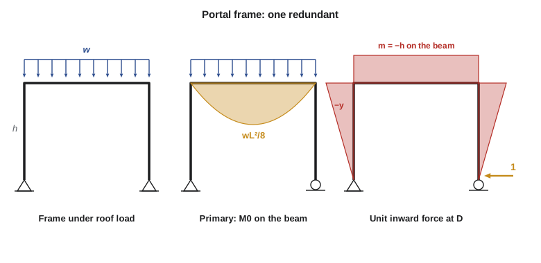
The garage roof is carried by single-bay rigid steel frames with pinned bases. Each frame has four reactions, so it is indeterminate to the first degree. The natural redundant is the horizontal reaction H at one base: releasing it to a roller leaves a determinate frame whose roof member behaves as a simple beam, while the columns carry no bending at all.
Worked problem
Pinned-base portal under roof load
A garage frame has columns \(h = 20\) ft high, a roof beam of span \(L = 60\) ft, constant \(EI\) throughout and a factored roof load of 0.82 kip/ft along the beam. Find the horizontal base reaction, the corner moments and the midspan moment.
Show solution
- Redundant: \(X_1 = H\), the horizontal reaction at D, taken as acting inward. Primary structure: pin at A, roller at D.
- Primary moments: zero in both columns; \(M_0 = wx(L - x)/2\) in the beam, sagging.
- Unit inward force at D: the moment is \(-y\) in each column at height y, and \(-h\) along the whole beam (hogging, with tension on the outside of the frame).
- Load displacement at D, from the beam only (the columns have no \(M_0\)):
- \[EI\,\Delta_{10} = \int_0^L (-h)\,\frac{wx(L - x)}{2}\,dx = -\frac{h\,wL^3}{12}\]
- Flexibility coefficient, from both columns and the beam:
- \[EI\,f_{11} = 2\int_0^h y^2\,dy + h^2 L = \frac{2h^3}{3} + h^2 L\]
- Compatibility: the base D does not move, so \(\Delta_{10} + f_{11}H = 0\):
- \[H = \frac{wL^3/12}{2h^2/3 + hL}\]
- \[H = \frac{0.82(60)^3/12}{2(20)^2/3 + 20(60)} = \frac{14\,760}{1467} = 10.06\ \text{kips}\]
- Corner moments: \(M_B = M_C = -Hh = -10.06(20) = -201.3\ \text{kip·ft}\). Midspan: \(wL^2/8 - Hh = 369.0 - 201.3 = 167.7\ \text{kip·ft}\).
Answer: Each base pushes outward on its footing with 10.1 kips, which the footing or a tie must resist. The rigid corners take 201 kip·ft of hogging moment and the midspan sagging moment drops to 168 kip·ft, less than half the 369 kip·ft of a simply supported roof beam.
Writing the result in terms of the relative stiffness \(k = (I_b/I_c)(h/L)\) of beam and columns gives a formula that shows how stiffness shares the moment:
With equal sections, \(k = h/L = 1/3\) for the garage frame. A stiffer beam (larger k) reduces H and the corner moments, sending more moment to midspan; stiffer columns (smaller k) do the reverse. In the limit of rigid columns, \(k \to 0\) and \(H \to wL^2/(12h)\), so the corner moment approaches the fixed-end moment \(wL^2/12\). This is the general character of indeterminate structures: moment goes where the stiffness is.
Compare the three-hinged salt shed frames of CIV-224. There the crown hinge fixes the thrust by statics at \(wL^2/(8h)\), regardless of member sizes. In the garage portal, removing that hinge lets the beam develop sagging moment at midspan, so the thrust is smaller, here about 55 percent of the three-hinged value, and depends on the section properties.
Frames with more redundants
Fixing the bases of the garage portal adds two more restraints, making it indeterminate to the third degree. A convenient primary structure is a cantilever frame: release all three reactions at D (\(H_D\), \(V_D\), \(M_D\)) and the frame becomes a bent cantilever fixed at A. The compatibility equations state that the horizontal displacement, vertical displacement and rotation at D are all zero, and the three-by-three flexibility matrix couples them.
A second strategy, which often reduces the arithmetic, is to cut the frame at its axis of symmetry. The internal forces at the cut of a symmetric frame (axial force, shear and moment) become the redundants. Under symmetric loading the shear at the cut is zero, and under antisymmetric loading the axial force and moment are zero, so the three equations split into smaller independent sets. Any load can be written as the sum of a symmetric and an antisymmetric part, which makes this a general method.
| Frame | Degree of indeterminacy | Good choice of redundants |
|---|---|---|
| Portal, pinned bases | 1 | Horizontal reaction at one base |
| Portal, fixed bases | 3 | All reactions at one base, or the forces at a cut at midspan |
| Two-bay portal, pinned bases | 3 | Horizontal reactions at two bases and the vertical reaction at the middle column |
| Gable frame, pinned bases | 1 | Horizontal reaction at one base |
| Closed rectangular box | 3 | Forces at a cut through one member |
Trusses: axial deformation only
In a pin-jointed truss the only deformation is the change of member length, so the virtual work integrals reduce to sums over the members. The coefficients of the compatibility equations become
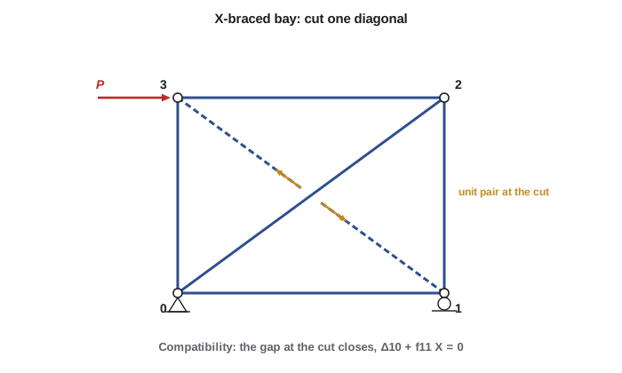
where \(N_0\) are the member forces in the primary truss under the loads and \(n_i\) the forces under a unit value of redundant i. A truss can be externally indeterminate (more supports than needed), internally indeterminate (more members than needed) or both. For an internal redundant, the primary truss is made by cutting the redundant member. The unit redundant is then a pair of equal and opposite unit forces applied to the two cut ends, and the compatibility condition is that the gap at the cut closes: the relative displacement of the two ends must be zero. The redundant member itself is part of the structure and contributes its own term \(1^2 L/AE\) to \(f_{ii}\).
Worked problem
X-braced wall bay
An X-braced garage wall bay is 20 ft wide and 15 ft high. Joint 0 is pinned and joint 1 is on a roller. A factored wind load of 13.5 kips acts horizontally at the top joint 3 above the pin. All six members have the same AE. Find the member forces.
Show solution
- Indeterminacy: \(b + r = 6 + 3 = 9\), \(2j = 8\), so one redundant. Cut diagonal 1–3 and take its force X (tension positive) as the redundant.
- Primary truss forces \(N_0\) by joints: top chord 2–3 \(-13.5\) kips, column 1–2 \(-10.1\) kips, diagonal 0–2 \(+16.9\) kips, others zero.
- Unit tension pair in diagonal 1–3: the chords take \(-0.8\), the columns \(-0.6\), and both diagonals \(+1.0\) (the ratios are those of the 3-4-5 triangle).
- \[AE\,\Delta_{10} = \sum n N_0 L = (-0.6)(-10.125)(15) + (-0.8)(-13.5)(20) + (1.0)(16.875)(25) = 729.0\]
- \[AE\,f_{11} = \sum n^2 L = 2(0.64)(20) + 2(0.36)(15) + 2(1.0)(25) = 86.40\]
- \[X = -\frac{729.0}{86.40} = -8.44\ \text{kips}\]
- Final forces by superposition, \(N = N_0 + X\,n\).
Answer: Diagonal 0–2 carries 8.44 kips tension and diagonal 1–3 carries 8.44 kips compression: with equal areas the two diagonals share the shear equally. The top chord drops from 13.5 to 6.75 kips compression and the bottom chord gains 6.75 kips tension. If the diagonals were slender rods that buckle at low load, the compression diagonal would drop out and the tension diagonal would carry the full 16.9 kips, which is the tension-only assumption commonly made for rod bracing.
A tabular layout keeps truss calculations organized: one row per member with columns for L, A, \(N_0\), n, \(nN_0L/A\) and \(n^2L/A\), and the two sums at the foot. The same table, extended with columns for further redundants, handles trusses with several redundant members or supports. When members have different areas, the stiffer members attract more force; doubling the area of diagonal 0–2 alone would raise its share of the shear above one half.
Solving it in code
The program below builds the joint equilibrium equations of the primary truss and solves them by Gaussian elimination, then applies the compatibility equation. Because the equilibrium solver is general, the same code handles any truss with one internal redundant: change the nodes, members, areas and loads. Try setting the area of diagonal 1–3 to 0.01 to imitate a slender rod and watch the force move into the other diagonal.
# Force method for a truss with one internal redundant (X-braced wall bay)
# Pure-Python Gaussian elimination solves the joint equilibrium equations.
b, h, P = 20.0, 15.0, 13.5                 # bay width, height (ft), wind load (kips)
nodes = [(0.0, 0.0), (b, 0.0), (b, h), (0.0, h)]
members = [(0, 1), (1, 2), (2, 3), (3, 0), (0, 2), (1, 3)]
A = [1.0, 1.0, 1.0, 1.0, 1.0, 1.0]         # relative areas (E cancels)
reactions = [(0, 0), (0, 1), (1, 1)]       # (node, direction): pin at 0, roller at 1
redundant = 5                              # cut member 1-3

def gauss(M, rhs):
    n = len(rhs); a = [row[:] + [rhs[i]] for i, row in enumerate(M)]
    for c in range(n):
        p = max(range(c, n), key=lambda r: abs(a[r][c])); a[c], a[p] = a[p], a[c]
        for r in range(c + 1, n):
            f = a[r][c] / a[c][c]
            for k in range(c, n + 1): a[r][k] -= f * a[c][k]
    x = [0.0] * n
    for r in range(n - 1, -1, -1):
        x[r] = (a[r][n] - sum(a[r][k] * x[k] for k in range(r + 1, n))) / a[r][r]
    return x

def geom(m):
    (xi, yi), (xj, yj) = nodes[members[m][0]], nodes[members[m][1]]
    L = ((xj - xi) ** 2 + (yj - yi) ** 2) ** 0.5
    return L, (xj - xi) / L, (yj - yi) / L

def solve_primary(loads, pair=0.0):
    # unknowns: forces in all members except the redundant, then reactions
    kept = [m for m in range(len(members)) if m != redundant]
    nu = len(kept) + len(reactions); E = [[0.0] * nu for _ in range(2 * len(nodes))]
    rhs = [-loads[d] for d in range(2 * len(nodes))]
    for col, m in enumerate(kept):
        L, c, s = geom(m); i, j = members[m]
        E[2 * i][col] += c; E[2 * i + 1][col] += s; E[2 * j][col] -= c; E[2 * j + 1][col] -= s
    for k, (nd, d) in enumerate(reactions): E[2 * nd + d][len(kept) + k] = 1.0
    if pair:                               # unit tension pair in the cut member
        L, c, s = geom(redundant); i, j = members[redundant]
        rhs[2 * i] -= c; rhs[2 * i + 1] -= s; rhs[2 * j] += c; rhs[2 * j + 1] += s
    x = gauss(E, rhs); N = [0.0] * len(members)
    for col, m in enumerate(kept): N[m] = x[col]
    N[redundant] = pair
    return N

loads = [0.0] * 8; loads[6] = P            # horizontal load at node 3
N0 = solve_primary(loads)                  # primary structure under the load
n1 = solve_primary([0.0] * 8, pair=1.0)    # primary structure, unit force in cut member
D10 = sum(N0[m] * n1[m] * geom(m)[0] / A[m] for m in range(6))
f11 = sum(n1[m] ** 2 * geom(m)[0] / A[m] for m in range(6))
X = -D10 / f11
print("compatibility: %.2f + %.3f X = 0  ->  X = %.2f kips" % (D10, f11, X))
z = lambda v: round(v, 6) + 0.0           # tidy -0.00 in the printout
for m, (i, j) in enumerate(members):
print("member %d-%d: N0 = %7.2f n = %6.3f N = %7.2f kips" % (i, j, z(N0[m]), z(n1[m]), z(N0[m] + X * n1[m])))compatibility: 729.00 + 86.400 X = 0 -> X = -8.44 kips member 0-1: N0 = 0.00 n = -0.800 N = 6.75 kips member 1-2: N0 = -10.12 n = -0.600 N = -5.06 kips member 2-3: N0 = -13.50 n = -0.800 N = -6.75 kips member 3-0: N0 = 0.00 n = -0.600 N = 5.06 kips member 0-2: N0 = 16.88 n = 1.000 N = 8.44 kips member 1-3: N0 = 0.00 n = 1.000 N = -8.44 kips
The two numbers in the compatibility line are \(AE\Delta_{10}\) and \(AEf_{11}\) from the hand calculation, and the member table repeats the superposition column by column. Agreement between hand and program results at this level of detail is the standard you should expect of any check calculation.
Common mistakes
MistakeIncluding only the column terms, or only the beam terms, in a frame flexibility coefficient.
InsteadIntegrate \(m_i m_j/EI\) over every member, using each member's own EI.
MistakeLeaving out the redundant member's own contribution when a truss member is cut.
InsteadThe cut member is still part of the structure; it adds \(1^2 L/AE\) to \(f_{11}\).
MistakeAssuming a portal's thrust equals the three-hinged value \(wL^2/(8h)\).
InsteadWithout a crown hinge the thrust depends on the beam-to-column stiffness ratio and is smaller.
MistakeAssuming both diagonals of rod bracing work in compression.
InsteadSlender rods buckle at very low load; design them as tension-only, with one diagonal active per load direction.
Summary and key terms
- Frames: bending dominates and axial and shear deformation are usually neglected in hand analysis.
- Pinned-base portal under uniform roof load: \(H = wL^2/[4h(3 + 2k)]\) with \(k = (I_b/I_c)(h/L)\).
- Fixed-base portals have three redundants; symmetry and antisymmetry split the equations.
- Trusses: \(\Delta_{i0} = \sum n_i N_0 L/AE\) and \(f_{ij} = \sum n_i n_j L/AE\).
- For an internal redundant, cut the member, apply a unit pair, and require the gap to close.
- Inextensible member
- A member whose axial deformation is neglected in the analysis.
- Relative stiffness
- The ratio of the stiffness EI/L of one member to that of another.
- Internal redundant
- A member that is not required for the stability of a truss or frame.
- Unit pair
- Equal and opposite unit forces applied to the two ends of a cut member.
- Tension-only bracing
- Bracing of slender rods or cables assumed to carry no compression.
- Antisymmetric load
- A load whose mirror image about the axis of symmetry is equal and opposite.
- Thrust
- The horizontal base reaction of a frame or arch under vertical load.
Practice problems
Work each problem on paper first, then reveal the answer to check.
Why does a portal frame with a stiffer beam have smaller corner moments under roof load?
Show answer
Moment goes where the stiffness is: a stiffer beam carries more of the load in its own sagging bending, so the columns restrain it less and H and the corner moments fall.
Find H for a pinned-base portal with \(h = 16\) ft, \(L = 48\) ft, equal EI and \(w = 0.7\) kip/ft.
Show answer
\(k = 1/3\): \(H = 0.7(2304)/[4(16)(3.667)] = 6.87\ \text{kips}\).
How many redundants does a two-bay portal with fixed bases have?
Show answer
Six: nine reactions minus three equations of statics.
In the X-bay example, what would the tension diagonal carry if the compression diagonal buckled?
Show answer
The full 16.9 kips, since the bay becomes a determinate truss.
What is the compatibility condition for a cut internal truss member?
Show answer
The relative displacement of the two cut ends along the member is zero.
When should the axial term be included in a frame force method calculation?
Show answer
When members carry large axial forces relative to bending, such as in Vierendeel chords, tied frames or tall frame columns.
Lesson quiz · 5 questions
Score 60% or more to complete this lesson.
Create a free account to save your progress, take quizzes and earn a certificate.