
CIV-321 · Lesson 5 of 12 · 22 min
Slope-deflection for beams
The force method takes forces as the unknowns and writes compatibility equations. The displacement methods do the reverse: they take joint displacements (rotations and translations) as the unknowns and write equilibrium equations at the joints. For most building structures the displacement methods need fewer unknowns, they do not require a choice of redundants, and they lead directly to the matrix stiffness method that every structural analysis program uses. The slope-deflection method, published in 1915 for the analysis of rigid frames, is the hand version of the displacement approach and the subject of this lesson and the next.
Force method versus displacement method
Consider a beam continuous over five supports with fixed ends. The force method needs as many unknowns as there are redundants: six here (three interior reactions plus two end moments plus one more end restraint, depending on the choice). The displacement method needs only the rotations of the joints that are free to rotate: three. For frames the advantage is often larger. The number of unknowns in the displacement method is the degree of kinematic indeterminacy from lesson 1, and the method is systematic: no judgment is needed about which restraints to release.
| Feature | Force (flexibility) method | Displacement (stiffness) method |
|---|---|---|
| Unknowns | Redundant forces | Joint rotations and translations |
| Equations written | Compatibility | Equilibrium at joints |
| Number of unknowns | Degree of static indeterminacy | Degree of kinematic indeterminacy |
| Choice involved | Which redundants to release | None: every free displacement is an unknown |
| Matrix form | \(\mathbf{F}\mathbf{X} = \boldsymbol{\Delta} - \boldsymbol{\Delta}_0\) | \(\mathbf{K}\mathbf{D} = \mathbf{P}\) |
| Computer use | Rare | Universal |
The slope-deflection equation
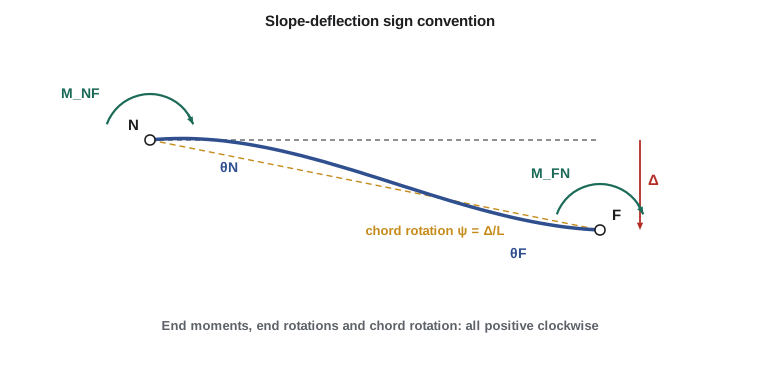
Take a member from near end N to far end F, of length L and constant \(EI\). Its end moments depend on four things: the rotation of each end, the relative transverse displacement of the ends, and the loads on the span. By superposing the effect of each, using the moment-area or conjugate beam results of CIV-224, we get the slope-deflection equation
The sign convention is the key to using it correctly. Moments acting on the end of the member, end rotations and the chord rotation \(\psi = \Delta/L\) are all positive clockwise. \(\text{FEM}_{NF}\) is the fixed-end moment at N caused by the span loads with both ends fully fixed; with this convention it is negative at the left end and positive at the right end for downward loads.
Each term has a physical meaning. A clockwise rotation \(\theta_N\) of the near end, with the far end fixed, needs a moment \(4EI\theta_N/L\) at the near end and induces \(2EI\theta_N/L\) at the far end. The factor of one half between them is the carryover that the moment distribution method of lesson 7 relies on. A chord rotation \(\psi\) with both ends fixed against rotation needs moments of \(-6EI\psi/L\) at each end, which is the settlement moment \(6EI\Delta/L^2\) of a fixed-fixed beam.
| Load case | \(\text{FEM}_{NF}\) (left end) | \(\text{FEM}_{FN}\) (right end) |
|---|---|---|
| Uniform load w over the span | \(-wL^2/12\) | \(+wL^2/12\) |
| Point load P at midspan | \(-PL/8\) | \(+PL/8\) |
| Point load P at a from N, b from F | \(-Pab^2/L^2\) | \(+Pa^2b/L^2\) |
| Triangular load, zero at N, w at F | \(-wL^2/30\) | \(+wL^2/20\) |
| Two equal loads P at third points | \(-2PL/9\) | \(+2PL/9\) |
| Settlement \(\Delta\) of F relative to N (no load) | \(-6EI\Delta/L^2\) | \(-6EI\Delta/L^2\) |
The procedure
- Identify the unknown joint rotations (and, for frames, translations). Fixed supports have \(\theta = 0\); pins, rollers and interior supports have unknown rotations.
- Compute the fixed-end moments for every loaded span.
- Write the two slope-deflection equations for every member, in terms of the unknowns.
- Write one equilibrium equation per unknown rotation: the sum of the member end moments at each joint equals any external moment applied there (zero for most joints). At a pinned end the single member end moment is zero.
- Solve the equations, substitute back to find all end moments, then find shears and reactions from free bodies of each span.
- Draw the shear and moment diagrams. Remember that a clockwise end moment on the left end of a span is a hogging moment, and a counterclockwise one on the right end is too; translate the signs before drawing.
The office wing floor beam
Worked problem
A two-span beam with a fixed end
An office wing floor beam is built into a concrete wall at A (fixed), passes over a column at B and ends on a pin at C. Span AB is 24 ft with a factored uniform load of 1.25 kip/ft; span BC is 20 ft with a factored point load of 13.5 kips at midspan from a mechanical unit. EI is constant. Find the end moments and reactions.
Show solution
- Unknowns: \(\theta_B\) and \(\theta_C\) (\(\theta_A = 0\)).
- \[\text{FEM}_{AB} = -\frac{1.25(24)^2}{12} = -60.00 \qquad \text{FEM}_{BA} = +60.00 \qquad \text{FEM}_{BC} = -\frac{13.5(20)}{8} = -33.75 \qquad \text{FEM}_{CB} = +33.75\]
- Slope-deflection equations (writing \(\theta\) for \(EI\theta\)):
- \[M_{AB} = 0.0833\theta_B - 60.00 \qquad M_{BA} = 0.1667\theta_B + 60.00\]
- \[M_{BC} = 0.2\theta_B + 0.1\theta_C - 33.75 \qquad M_{CB} = 0.2\theta_C + 0.1\theta_B + 33.75\]
- Equilibrium at B: \(M_{BA} + M_{BC} = 0 \to 0.3667\theta_B + 0.1\theta_C = -26.25\). At the pin C: \(M_{CB} = 0 \to 0.1\theta_B + 0.2\theta_C = -33.75\).
- Solving: \(EI\theta_B = -29.61\ \text{kip·ft}^2\), \(EI\theta_C = -153.95\ \text{kip·ft}^2\) (both counterclockwise).
- \[M_{AB} = -62.47\ \text{kip·ft} \qquad M_{BA} = +55.07\ \text{kip·ft} \qquad M_{BC} = -55.07\ \text{kip·ft} \qquad M_{CB} = 0\]
- Span AB free body: \(V_A = wL/2 + (62.47 - 55.07)/24 = 15.00 + 0.31 = 15.31\) kips, \(V_{BA} = 30.0 - 15.31 = 14.69\) kips. Span BC: \(V_C = 6.75 - 55.07/20 = 4.00\) kips, \(V_{BC} = 9.50\) kips.
Answer: The wall at A takes a hogging moment of 62.5 kip·ft and the column at B a hogging moment of 55.1 kip·ft. Reactions: \(R_A = 15.3\) kips, \(R_B = 14.7 + 9.5 = 24.2\) kips, \(R_C = 4.0\) kips, totaling the applied 43.5 kips. The maximum sagging moment in AB is 31.3 kip·ft at 12.25 ft from A, where the shear is zero, and the moment under the point load in BC is \(4.00(10) = 40.0\) kip·ft.
Check the answer the way an experienced engineer would. The moment at A exceeds the fixed-end value \(wL^2/12\) because B rotates counterclockwise, which lets span AB sag more near B and throws moment back toward A. The moment at B lies between the fixed-end moments of the two spans, as it must when the joint rotates to balance them. And the sum of reactions equals the total load.
Pinned ends: the modified equation
When the far end of a member is a pin or roller with no external moment, its end moment is zero and its rotation is not needed for anything else. Eliminating \(\theta_F\) from the pair of slope-deflection equations gives the modified equation for the near end:
For span BC of the example: \(M_{BC} = 0.15\theta_B - 33.75 - 16.875 = 0.15\theta_B - 50.625\). Joint B then gives a single equation, \(0.1667\theta_B + 60.00 + 0.15\theta_B - 50.625 = 0\), so \(\theta_B = -9.375/0.3167 = -29.61\), the same as before with one unknown fewer. The term \(-50.625\) is the fixed-end moment of a propped cantilever under a central point load, \(3PL/16\).
Use the modified equation whenever an end pin or roller carries no applied moment. A cantilever overhang beyond the last support is handled differently: it is determinate, so its moment at the support is known from statics and enters the joint equilibrium equation as an external moment.
Support settlement
Settlement enters slope-deflection through the chord rotation. If support B of a beam settles by \(\Delta\), span AB rotates clockwise by \(\psi_{AB} = \Delta/L_{AB}\) and span BC rotates counterclockwise by \(\psi_{BC} = -\Delta/L_{BC}\). These known values go into the equations with the loads; the unknowns are still only the joint rotations. This is often quicker than the force method treatment of lesson 4, and the two must give identical answers.
Solving it in code
The program assembles the joint equilibrium equations from the slope-deflection equations of each span and solves them by Gaussian elimination. It handles any number of spans, fixed or free joints, and a uniform load plus one point load per span. Each span's contribution to the equations is added into a coefficient matrix exactly as a stiffness matrix is assembled in lesson 10, a link worth noticing now.
# Slope-deflection method for a continuous beam (no sway), solved by Gaussian elimination
# Sign convention: end moments and rotations positive clockwise.
spans = [  # length (ft), relative EI, uniform load (kip/ft), point load (kips), its distance from left end (ft)
    (24.0, 1.0, 1.25, 0.0, 0.0),       # span AB
    (20.0, 1.0, 0.0, 13.5, 10.0),      # span BC
]
fixed = [True, False, False]           # rotation restrained at joints A, B, C?

def fem(L, w, P, a):                   # fixed-end moments (clockwise positive) at left and right ends
    b = L - a
    return (-w * L ** 2 / 12 - P * a * b ** 2 / L ** 2, w * L ** 2 / 12 + P * a ** 2 * b / L ** 2)

def gauss(A, r):
    n = len(r); M = [row[:] + [r[i]] for i, row in enumerate(A)]
    for c in range(n):
        p = max(range(c, n), key=lambda k: abs(M[k][c])); M[c], M[p] = M[p], M[c]
        for k in range(c + 1, n):
            f = M[k][c] / M[c][c]
            for j in range(c, n + 1): M[k][j] -= f * M[c][j]
    x = [0.0] * n
    for k in range(n - 1, -1, -1):
        x[k] = (M[k][n] - sum(M[k][j] * x[j] for j in range(k + 1, n))) / M[k][k]
    return x

free = [j for j in range(len(fixed)) if not fixed[j]]      # joints whose rotation is unknown
idx = dict((j, i) for i, j in enumerate(free))
K = [[0.0] * len(free) for _ in free]; R = [0.0] * len(free)
for s, (L, EI, w, P, a) in enumerate(spans):
    k = 2 * EI / L; Fl, Fr = fem(L, w, P, a)
    # M_left = k(2 th_l + th_r) + Fl,  M_right = k(2 th_r + th_l) + Fr; joint equations sum to zero
    for jn, Fe, coef in ((s, Fl, (2 * k, k)), (s + 1, Fr, (k, 2 * k))):
        if jn in idx:
            R[idx[jn]] -= Fe
            for jj, c in zip((s, s + 1), coef):
                if jj in idx: K[idx[jn]][idx[jj]] += c
z = lambda v: round(v, 6) + 0.0           # tidy -0.00 in the printout
theta = [0.0] * len(fixed)
for j, t in zip(free, gauss(K, R)): theta[j] = t
print("EI x rotations (kip*ft^2):", [round(z(t), 2) for t in theta])
for s, (L, EI, w, P, a) in enumerate(spans):
    k = 2 * EI / L; Fl, Fr = fem(L, w, P, a)
    Ml = k * (2 * theta[s] + theta[s + 1]) + Fl
    Mr = k * (2 * theta[s + 1] + theta[s]) + Fr
    Vl = (w * L * L / 2 + P * (L - a) - Ml - Mr) / L          # left-end shear, upward
    print("span %d: M_left = %7.2f  M_right = %7.2f kip*ft  V_left = %6.2f  V_right = %6.2f kips"
% (s + 1, z(Ml), z(Mr), Vl, w * L + P - Vl))EI x rotations (kip*ft^2): [0.0, -29.61, -153.95] span 1: M_left = -62.47 M_right = 55.07 kip*ft V_left = 15.31 V_right = 14.69 kips span 2: M_left = -55.07 M_right = 0.00 kip*ft V_left = 9.50 V_right = 4.00 kips
The printed rotations match the hand solution, and the right-end shear of span 1 plus the left-end shear of span 2 give the reaction at B. Set the first entry of the fixed list to False to make A a pin, or add a third span, and compare with your own hand solutions.
Common mistakes
MistakeMixing beam sign conventions (sagging positive) with slope-deflection signs (clockwise positive).
InsteadWork in clockwise-positive end moments throughout, and convert to hogging and sagging only when drawing diagrams.
MistakeGiving the fixed-end moments the wrong sign at one end.
InsteadFor downward load, FEM is negative at the left end and positive at the right end.
MistakeWriting an equilibrium equation at a fixed support.
InsteadA fixed support has a known rotation (zero) and an unknown reaction moment; the equilibrium equations belong to joints with unknown rotations.
MistakeForgetting the external moment from an overhang in the joint equation.
InsteadInclude the cantilever moment as an applied moment at that joint.
Summary and key terms
- Slope-deflection: \(M_{NF} = (2EI/L)(2\theta_N + \theta_F - 3\psi) + \text{FEM}_{NF}\), all clockwise positive.
- Unknowns are joint rotations; equations are moment equilibrium at those joints.
- A pinned far end gives \(M_{NF} = (3EI/L)(\theta_N - \psi) + \text{FEM}_{NF} - \text{FEM}_{FN}/2\).
- Settlement enters through the known chord rotation \(\psi = \Delta/L\).
- Displacement methods need fewer unknowns than force methods for most building structures and lead to the stiffness method.
- Displacement method
- An analysis method whose unknowns are joint displacements and whose equations are equilibrium equations.
- Slope-deflection equation
- The relation between the end moments of a member and its end rotations, chord rotation and loads.
- Chord rotation
- The rotation of the straight line joining the two ends of a member, equal to relative transverse displacement over length.
- Fixed-end moment
- The end moment of a member under its span loads with both ends fixed.
- Carryover
- The moment induced at the far fixed end of a member by a rotation at the near end; half of the near-end moment.
- Modified slope-deflection equation
- The form of the equation for a member whose far end is pinned.
- Stiffness
- The moment or force required to produce a unit rotation or displacement.
Practice problems
Work each problem on paper first, then reveal the answer to check.
What moment is needed at the near end of a member with constant EI to rotate it by \(\theta\) when the far end is fixed? What moment appears at the far end?
Show answer
\(4EI\theta/L\) at the near end and \(2EI\theta/L\) at the far end.
Find the fixed-end moments for a 16 ft span with a 9 kip point load 6 ft from the left end.
Show answer
\(\text{FEM}_{NF} = -9(6)(10)^2/256 = -21.1\) kip·ft; \(\text{FEM}_{FN} = +9(6)^2(10)/256 = +12.7\) kip·ft.
How many unknowns does slope-deflection need for a four-span continuous beam on pins and rollers with no sway?
Show answer
Five rotations, or three if the modified equation is used for the two end spans.
What is the chord rotation of a 20 ft span whose right support settles 0.48 in.?
Show answer
\(\psi = 0.04/20 = 0.002\) rad, clockwise.
Why does the moment at A in the example exceed \(wL^2/12\)?
Show answer
Joint B rotates, releasing restraint at B and throwing moment back to the fixed end A.
For a fixed-fixed beam with a central point load, what is the moment at midspan?
Show answer
\(PL/4 - PL/8 = PL/8\), sagging.
Lesson quiz · 5 questions
Score 60% or more to complete this lesson.
Create a free account to save your progress, take quizzes and earn a certificate.