
CIV-321 · Lesson 10 of 12 · 22 min
Matrix stiffness method II: beams
A truss member resists only stretching. A beam element resists bending, so each of its nodes has a transverse displacement and a rotation. This lesson builds the 4 × 4 beam element stiffness matrix, shows how loads applied between nodes are converted into equivalent joint loads, and solves the continuous beams of lessons 4 and 5 by the stiffness method. The result is a general beam program that handles any number of spans, fixed and pinned supports, and support settlements, all with the same few lines of code.
Degrees of freedom for a beam
For a straight beam along the x axis, ignoring axial deformation, each node has two degrees of freedom: a vertical displacement v (positive upward) and a rotation \(\theta\) (positive counterclockwise). Matrix methods conventionally use this right-handed convention rather than the clockwise-positive convention of slope-deflection. The numbers are identical, only the signs differ, so be careful when comparing results: a counterclockwise rotation of \(20.87/EI\) in this lesson is the \(\theta_B = -20.87/EI\) of lesson 5.
Nodes are placed at every support, at every change of section, and at any point where you want displacements reported. Supports restrain degrees of freedom: a pin or roller restrains v; a fixed support restrains both v and \(\theta\); a free end or an interior node restrains neither. An internal hinge is modeled either by giving the element a released end (a modified element matrix) or by two nodes at the same location sharing v but not \(\theta\).
The beam element stiffness matrix
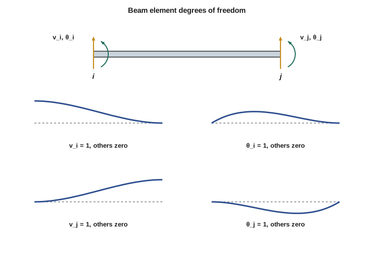
Column j of the element matrix holds the end forces needed to produce a unit value of degree of freedom j with the other three held at zero. Each of these four shapes is a fixed-ended beam with one end displaced or rotated, so the end forces come straight from the slope-deflection equation of lesson 5 and from equilibrium of the element. A unit rotation at i needs a moment \(4EI/L\) there, induces \(2EI/L\) at j, and needs shears of \(\pm 6EI/L^2\) to keep the element in equilibrium. A unit transverse displacement at i, with no rotation, needs end moments of \(6EI/L^2\) and shears of \(\pm 12EI/L^3\). Collecting all four columns:
The matrix is symmetric and singular: it has two rigid-body modes, a uniform translation and a small rigid rotation, which produce no end forces. A beam element is exact for a prismatic member under end loads, because the cubic deflected shape assumed in its derivation is the true elastic curve when there is no load between the nodes. That is a property worth remembering: one element per span gives exact end moments, with no mesh refinement needed.
Loads between nodes
The stiffness method applies loads at nodes. Loads along an element are converted by the fixed-end idea used in slope-deflection: first lock the nodes and compute the fixed-end forces \(\mathbf{q}_F\) that the locked ends would supply; then release the nodes by applying the opposite of these forces as equivalent joint loads.
The equivalent joint loads, \(-\mathbf{q}_F\), are added into the structure load vector. After solving for the displacements, the true end forces of each element are the stiffness response plus the fixed-end forces:
Forgetting to add \(\mathbf{q}_F\) back is one of the most common errors in hand-coded stiffness programs: the joint displacements come out right, but the end moments of loaded members are wrong by exactly the fixed-end moments.
| Load on element | \(V_i\) | \(M_i\) | \(V_j\) | \(M_j\) |
|---|---|---|---|---|
| Uniform w over L | \(wL/2\) | \(wL^2/12\) | \(wL/2\) | \(-wL^2/12\) |
| Point P at midspan | \(P/2\) | \(PL/8\) | \(P/2\) | \(-PL/8\) |
| Point P at a from i, b from j | \(Pb^2(3a + b)/L^3\) | \(Pab^2/L^2\) | \(Pa^2(a + 3b)/L^3\) | \(-Pa^2b/L^2\) |
The office floor beam again
Worked problem
Two-span beam by the stiffness method
Solve the floor beam of lesson 5 (A fixed; B on a column; C pinned; AB 24 ft with 1.25 kip/ft; BC 20 ft with 13.5 kips at midspan; constant EI) by the stiffness method.
Show solution
- Nodes A, B, C with six degrees of freedom. Restrained: \(v_A\), \(\theta_A\), \(v_B\), \(v_C\). Free: \(\theta_B\) and \(\theta_C\).
- Only the rotational terms of each element matrix enter \(\mathbf{K}_{ff}\). Element AB contributes \(4EI/L_1\) at \(\theta_B\); element BC contributes \(4EI/L_2\) at \(\theta_B\) and at \(\theta_C\), and \(2EI/L_2\) to the coupling.
- \[\mathbf{K}_{ff} = EI\begin{bmatrix} 4/24 + 4/20 & 2/20 \\ 2/20 & 4/20 \end{bmatrix} = EI\begin{bmatrix} 0.3667 & 0.1000 \\ 0.1000 & 0.2000 \end{bmatrix}\]
- Equivalent joint moments: at B, \(+wL_1^2/12\) from AB and \(-PL_2/8\) from BC, \(60.00 - 33.75 = 26.25\); at C, \(+PL_2/8 = 33.75\ \text{kip·ft}\).
- \[EI\begin{bmatrix} 0.3667 & 0.1000 \\ 0.1000 & 0.2000 \end{bmatrix}\begin{bmatrix} \theta_B \\ \theta_C \end{bmatrix} = \begin{bmatrix} 26.25 \\ 33.75 \end{bmatrix} \quad\to\quad EI\theta_B = 29.61,\ EI\theta_C = 153.95\]
- End moments of AB from \(\mathbf{q} = \mathbf{k}\mathbf{d} + \mathbf{q}_F\): \(M_A = (2EI/24)\theta_B + 60.00 = 2.47 + 60.00 = 62.47\) and \(M_B = (4EI/24)\theta_B - 60.00 = -55.07\ \text{kip·ft}\).
- Reactions come from the restrained rows of the assembled system, or from the element end shears.
Answer: The stiffness matrix and load vector are exactly the slope-deflection equations of lesson 5, written in matrix form with the opposite sign convention, so the answers are identical: 62.5 kip·ft at the wall and 55.1 kip·ft over the column.
The correspondence is not a coincidence. Slope-deflection is the stiffness method with the free degrees of freedom chosen by hand and the support translations eliminated in advance. The matrix version keeps every degree of freedom and lets the partitioning step remove the restrained ones, which is what makes it automatic.
Settlements, springs and hinges
Support settlement is a prescribed displacement. Set the settled value in \(\mathbf{D}_s\) and move its effect to the right-hand side: \(\mathbf{K}_{ff}\mathbf{D}_f = \mathbf{P}_f - \mathbf{K}_{fs}\mathbf{D}_s\). This reproduces the settlement results of lesson 4 without any flexibility coefficients. An elastic support (a footing on soil, or a beam resting on a flexible girder) is a spring: its stiffness k is simply added to the diagonal term of the corresponding degree of freedom, and the support is then treated as free. A rotational spring at a support models a partially fixed connection in the same way, which is how semi-rigid connections are represented in practice.
Programs model internal hinges by releasing the moment at an element end. For a release at end j, the element matrix is condensed to the propped-cantilever form, in which the \(4EI/L\) term at i becomes \(3EI/L\), just as in the modified slope-deflection equation. The released rotation is then excluded from the structure's degrees of freedom at that end. Releasing both ends of every element turns a beam model into a truss model, which is a handy check of the release logic.
Solving it in code
The program below is a complete continuous-beam stiffness solver. It assembles element matrices and equivalent joint loads, partitions out the restrained degrees of freedom, includes prescribed settlements, solves by Gaussian elimination and recovers element end forces. Model 1 repeats the hand example. Model 2 repeats the settlement case of lesson 4.
# Matrix stiffness method for continuous beams (2 DOF per node: v up, rotation counterclockwise)
def gauss(A, b):
    n = len(b); M = [row[:] + [b[i]] for i, row in enumerate(A)]
    for c in range(n):
        p = max(range(c, n), key=lambda r: abs(M[r][c]))
        if abs(M[p][c]) < 1e-12: raise ValueError("singular stiffness matrix: the model is unstable")
        M[c], M[p] = M[p], M[c]
        for r in range(c + 1, n):
            f = M[r][c] / M[c][c]
            for k in range(c, n + 1): M[r][k] -= f * M[c][k]
    x = [0.0] * n
    for r in range(n - 1, -1, -1):
        x[r] = (M[r][n] - sum(M[r][k] * x[k] for k in range(r + 1, n))) / M[r][r]
    return x

def k_beam(EI, L):
    a, b, c, d = 12 * EI / L ** 3, 6 * EI / L ** 2, 4 * EI / L, 2 * EI / L
    return [[a, b, -a, b], [b, c, -b, d], [-a, -b, a, -b], [b, d, -b, c]]

def fixed_end(L, w, P, x):          # member end forces with both ends fixed: [V_i, M_i, V_j, M_j]
    b = L - x
    return [w * L / 2 + P * b * b * (3 * x + b) / L ** 3, w * L * L / 12 + P * x * b * b / L ** 2,
            w * L / 2 + P * x * x * (x + 3 * b) / L ** 3, -w * L * L / 12 - P * x * x * b / L ** 2]

def solve_model(xs, elems, restrained, settle=()):
    """xs: node positions; elems: (i, j, EI, w, P, a); restrained: DOF numbers; settle: (DOF, value)"""
    n = 2 * len(xs); K = [[0.0] * n for _ in range(n)]; F = [0.0] * n
    for i, j, EI, w, P, a in elems:
        L = xs[j] - xs[i]; k = k_beam(EI, L); fe = fixed_end(L, w, P, a)
        dofs = [2 * i, 2 * i + 1, 2 * j, 2 * j + 1]
        for r in range(4):
            F[dofs[r]] -= fe[r]                    # equivalent joint loads
            for c in range(4): K[dofs[r]][dofs[c]] += k[r][c]
    D = [0.0] * n
    for d, val in settle: D[d] = val
    free = [d for d in range(n) if d not in restrained]
    rhs = [F[r] - sum(K[r][c] * D[c] for c in restrained) for r in free]
    for d, val in zip(free, gauss([[K[r][c] for c in free] for r in free], rhs)): D[d] = val
    ends = []
    for i, j, EI, w, P, a in elems:
        L = xs[j] - xs[i]; k = k_beam(EI, L); fe = fixed_end(L, w, P, a)
        dofs = [2 * i, 2 * i + 1, 2 * j, 2 * j + 1]
        ends.append([sum(k[r][c] * D[dofs[c]] for c in range(4)) + fe[r] for r in range(4)])
    return D, ends

z = lambda v: round(v, 4) + 0.0
# Model 1: lesson 5 office floor beam, fixed at A, column at B, pin at C (EI = 1 gives EI x rotation)
D, ends = solve_model([0.0, 24.0, 44.0], [(0, 1, 1.0, 1.25, 0.0, 0.0), (1, 2, 1.0, 0.0, 13.5, 10.0)],
                  restrained=[0, 1, 2, 4])
print("model 1: EI x rotation at B = %.2f, at C = %.2f (counterclockwise +)" % (D[3], D[5]))
for e, (V1, M1, V2, M2) in enumerate(ends):
    print("  member %d: V_i %.2f kips, M_i %.2f kip*ft, V_j %.2f kips, M_j %.2f kip*ft" % (e + 1, V1, z(M1), V2, z(M2)))
# Model 2: lesson 4 corridor beam, EI = 72 000 kip*ft^2, support B settles 0.4 in., no load
D, ends = solve_model([0.0, 20.0, 40.0, 60.0], [(0, 1, 7.2e4, 0, 0, 0), (1, 2, 7.2e4, 0, 0, 0), (2, 3, 7.2e4, 0, 0, 0)],
                  restrained=[0, 2, 4, 6], settle=[(2, -0.4 / 12)])
print("model 2: moments at B = %.2f and at C = %.2f kip*ft (sagging +)" % (ends[0][3], ends[1][3]))model 1: EI x rotation at B = 29.61, at C = 153.95 (counterclockwise +) member 1: V_i 15.31 kips, M_i 62.47 kip*ft, V_j 14.69 kips, M_j -55.07 kip*ft member 2: V_i 9.50 kips, M_i 55.07 kip*ft, V_j 4.00 kips, M_j 0.00 kip*ft model 2: moments at B = 21.60 and at C = -14.40 kip*ft (sagging +)
Model 1 reproduces the rotations and end forces above, and the shears 14.69 + 9.50 = 24.19 kips give the column reaction at B. Model 2 gives \(+21.6\) kip·ft over B and \(-14.4\) kip·ft over C, the force method answer of lesson 4, from a model that needed no redundants at all. A singular-matrix check in the solver catches unstable models: try restraining only the vertical displacement at A in model 1 and removing the column at B.
Displacements between nodes are not computed by the program. To see the deflected shape of a span, either add intermediate nodes (which does not change the end moments, since the element is exact) or evaluate the cubic shape functions with the element end displacements and add the fixed-end deflection of the span load. Commercial programs do the second automatically when they draw deflected shapes.
Common mistakes
MistakeUsing clockwise-positive slope-deflection signs in a counterclockwise-positive matrix program.
InsteadChoose one convention per calculation; matrix methods use v upward and \(\theta\) counterclockwise.
MistakeForgetting to add the fixed-end forces back to the element end forces.
InsteadUse \(\mathbf{q} = \mathbf{k}\mathbf{d} + \mathbf{q}_F\) for every loaded element.
MistakeApplying span loads directly as nodal forces at the nearest node.
InsteadConvert them to equivalent joint loads, including the fixed-end moments, or the moments will be wrong.
MistakeSubdividing spans to improve the accuracy of end moments.
InsteadOne element per prismatic span is already exact; subdivide only for displacement output or varying sections.
Summary and key terms
- Beam element: 4 × 4 matrix in \(v_i, \theta_i, v_j, \theta_j\) with terms \(12EI/L^3\), \(6EI/L^2\), \(4EI/L\), \(2EI/L\).
- Span loads become equivalent joint loads \(-\mathbf{q}_F\); end forces are \(\mathbf{k}\mathbf{d} + \mathbf{q}_F\).
- Settlements are prescribed displacements; springs add to diagonal terms; hinges are end releases.
- The stiffness matrix for rotation unknowns is the slope-deflection system in matrix form.
- One element per prismatic span gives exact end forces.
- Beam element
- A two-node element with transverse displacement and rotation at each node.
- Equivalent joint load
- A nodal force or moment that replaces a load applied between nodes.
- Fixed-end forces
- End forces of an element under its span loads with both ends restrained.
- Prescribed displacement
- A known displacement at a restrained degree of freedom, such as a settlement.
- End release
- A modeling device that sets an element end force, usually the moment, to zero.
- Shape function
- A function giving the displacement along an element from its end displacements.
- Rigid-body mode
- A displacement pattern of an unsupported element that produces no internal force.
Practice problems
Work each problem on paper first, then reveal the answer to check.
What are the four terms in the first column of the beam element matrix, and what do they represent?
Show answer
\(12EI/L^3\), \(6EI/L^2\), \(-12EI/L^3\), \(6EI/L^2\): the end shears and moments needed to give a unit upward displacement at i with the other three degrees of freedom fixed.
How many free degrees of freedom does a three-span beam on four pins and rollers have?
Show answer
Four, the rotations at the four supports.
How is a column that supports a beam but shortens elastically modeled?
Show answer
As a vertical spring of stiffness \(AE/L\) of the column, added to the diagonal term of the beam node.
Write the equivalent joint loads for a 20 ft element with 0.7 kip/ft.
Show answer
\(-7.0\) kips and \(-23.3\) kip·ft at i; \(-7.0\) kips and \(+23.3\) kip·ft at j.
Why is the beam element exact for a prismatic member without span loads?
Show answer
The cubic shape assumed in its derivation is the exact elastic curve for a beam loaded only at its ends.
What happens to the element matrix when a hinge releases the moment at end j?
Show answer
It condenses to the propped-cantilever form, with \(3EI/L\) in place of \(4EI/L\) at end i.
Lesson quiz · 5 questions
Score 60% or more to complete this lesson.
Create a free account to save your progress, take quizzes and earn a certificate.