
CIV-321 · Lesson 2 of 12 · 23 min
The force method for beams
Lesson 1 reviewed the force method for a beam with one redundant. Real continuous beams usually have several. The corridor beams in the office wing, for example, run continuously over three spans, and the access road girder may be built as two or three continuous spans. This lesson extends the force method to any number of redundants, introduces the flexibility matrix, derives the fixed-end moments that the displacement methods of later lessons rely on, and shows how the arrangement of live load changes the governing moments.
The general procedure
The force method has the same five steps whatever the number of redundants.
- Find the degree of indeterminacy n and choose n redundants \(X_1, X_2, \ldots, X_n\). Releasing them must leave a stable, determinate primary structure.
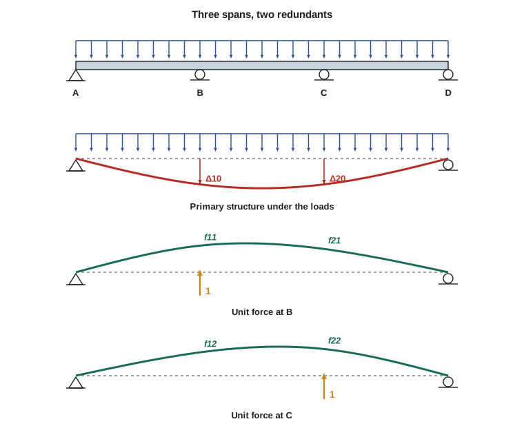
- Apply the actual loads to the primary structure and compute the displacement \(\Delta_{i0}\) at each redundant, in the direction of that redundant.
- Apply a unit value of each redundant in turn and compute the displacements \(f_{ij}\): the displacement at redundant i caused by a unit value of redundant j. These are the flexibility coefficients.
- Write one compatibility equation per redundant. Superposition gives the total displacement at each released point, which must equal the actual displacement there (zero at an unyielding support):
- Solve the n simultaneous equations for the redundants, then find every other reaction and internal force by equilibrium.
In matrix form the compatibility equations are \(\mathbf{F}\mathbf{X} = \boldsymbol{\Delta} - \boldsymbol{\Delta}_0\), where \(\mathbf{F}\) is the flexibility matrix of the primary structure. By Maxwell's reciprocal theorem \(f_{ij} = f_{ji}\), so \(\mathbf{F}\) is symmetric, which halves the number of coefficients you must compute. Its diagonal terms \(f_{ii}\) are always positive, because a force always moves its own point of application in its own direction.
Computing the coefficients
Every \(\Delta_{i0}\) and \(f_{ij}\) is a deflection of the determinate primary structure, so any method from CIV-224 lessons 10 and 11 will do. For beams the most efficient is usually the virtual work integral
where \(m_i\) is the moment diagram of the primary structure under a unit value of redundant i and \(M_0\) is its moment diagram under the loads. For members of constant \(EI\), product-integral tables (the visual integration table of CIV-224 lesson 11) give these integrals directly from the shapes of the diagrams: triangles, rectangles and parabolas. Standard deflection formulas from a beam handbook are equally valid when the primary structure is a simple beam or a cantilever.
Choosing redundants well saves work. Releasing interior support reactions of a continuous beam leaves a simple beam, whose deflections are well known but whose flexibility matrix is fully populated. Releasing the bending moments over the interior supports, by inserting hinges there, leaves a chain of simple spans; each unit moment then affects only the two adjacent spans, so the flexibility matrix is tridiagonal. For long continuous beams the second choice leads to the classical three-moment equation.
Three spans: two redundants
Worked problem
A three-span corridor beam
An office corridor beam is continuous over four supports A, B, C, D with three equal spans of 20 ft and constant \(EI\). It carries a factored uniform load of 1.0 kip/ft on all spans. Find the interior reactions and the moment over B.
Show solution
- Degree of indeterminacy: \(r = 5\), so \(n = 2\). Choose \(R_B = X_1\) and \(R_C = X_2\), upward. The primary structure is a simple beam of span \(3L\).
- Load deflections at B and C, from the handbook formula for a uniformly loaded simple beam evaluated at \(x = L\) on a span of \(3L\), downward:
- \[\Delta_{10} = \Delta_{20} = \frac{w x\,(l^3 - 2lx^2 + x^3)}{24EI} = \frac{wL\,(27L^3 - 6L^3 + L^3)}{24EI} = \frac{11wL^4}{12EI}\]
- Flexibility coefficients from the point-load deflection formula for a simple beam of span \(3L\):
- \[f_{11} = f_{22} = \frac{a^2b^2}{3EIl} = \frac{L^2(2L)^2}{3EI(3L)} = \frac{4L^3}{9EI} \qquad f_{12} = f_{21} = \frac{7L^3}{18EI}\]
- Compatibility at B (upward positive): \(-\frac{11wL^4}{12} + \frac{4L^3}{9}X_1 + \frac{7L^3}{18}X_2 = 0\), and the same with the subscripts swapped at C.
- By symmetry \(X_1 = X_2 = X\), so \(\Big(\tfrac{8}{18} + \tfrac{7}{18}\Big)X = \tfrac{11}{12}wL\), giving \(X = 1.1wL\).
- \[R_B = R_C = 1.1(1.0)(20) = 22.0\ \text{kips} \qquad R_A = R_D = \frac{3wL - 2(1.1wL)}{2} = 0.4wL = 8.0\ \text{kips}\]
- Moment over B from the free body AB: \(M_B = R_A L - wL^2/2 = 8.0(20) - 1.0(20)^2/2 = -40.0\ \text{kip·ft}\), that is \(-0.1wL^2\).
Answer: The interior supports each carry 22.0 kips and the end supports 8.0 kips. The hogging moment over each interior support is 40.0 kip·ft. The largest sagging moment, in the end spans, is \(0.08wL^2 = 32.0\ \text{kip·ft}\) at \(0.4L\) from the end; the middle span sags only \(0.025wL^2 = 10.0\ \text{kip·ft}\). Three simple spans would each have \(wL^2/8 = 50.0\ \text{kip·ft}\).
The coefficients 0.4, 1.1 and 0.1 are worth remembering: they appear in beam tables, and they give an immediate check on any computer model of a three-span beam with equal spans and uniform load.
Fixed-end moments by the force method
A beam fixed at both ends is indeterminate to the second degree for vertical loads (the horizontal reaction is not involved). Releasing the two end moments leaves a simple beam, and the redundants are the moments \(M_A\) and \(M_B\). The compatibility conditions are that the end rotations are zero.
Worked problem
Fixed-end moments for a uniform load
Find the end moments of a fixed-fixed beam of span L and constant \(EI\) carrying a uniform load w.
Show solution
- Primary structure: a simple beam. End rotations under the load: \(\theta_{A0} = \theta_{B0} = wL^3/(24EI)\).
- A unit moment applied at one end of a simple beam rotates that end by \(L/(3EI)\) and the far end by \(L/(6EI)\). These are the flexibility coefficients: \(f_{AA} = f_{BB} = L/(3EI)\), \(f_{AB} = f_{BA} = L/(6EI)\).
- Compatibility at A, with the redundant moments acting to reduce the rotation: \(\frac{wL^3}{24EI} - \frac{L}{3EI}M_A - \frac{L}{6EI}M_B = 0\), and similarly at B.
- By symmetry \(M_A = M_B = M\): \(M\Big(\tfrac{1}{3} + \tfrac{1}{6}\Big)L = \tfrac{wL^3}{24}\), so \(M = wL^2/12\).
Answer: The fixed-end moments are \(wL^2/12\) (hogging) at each end, and the midspan moment is \(wL^2/8 - wL^2/12 = wL^2/24\). The same procedure gives \(PL/8\) for a central point load and \(Pab^2/L^2\), \(Pa^2b/L^2\) for an eccentric point load. Lesson 5 collects these results in a table and uses them as the starting point of the slope-deflection method.
Pattern loading
Dead load is always present on every span, but live load and snow can occupy any combination of spans. In a determinate beam the worst case is always the fully loaded span. In a continuous beam it is not, because load on one span lifts the adjacent spans. Lesson 8 shows how influence lines identify the governing patterns; the rules for a continuous beam are:
- For the maximum sagging moment in a span, load that span and every second span from it, leaving the adjacent spans unloaded.
- For the maximum hogging moment over a support, load the two spans adjacent to that support and then every second span beyond them.
- For the maximum reaction at a support, load the adjacent spans in the same way as for hogging moment.
| Live load pattern | Span AB maximum (kip·ft) | Moment over B (kip·ft) | Span BC midspan (kip·ft) |
|---|---|---|---|
| All spans loaded | 32.0 | −40.0 | 10.0 |
| Spans AB and CD loaded | 37.0 | −28.0 | −8.0 |
| Span BC only loaded | 8.5 | −28.0 | 22.0 |
| Spans AB and BC loaded | 30.4 | −44.0 | — |
Loading alternate spans raises the end-span moment by about 16 percent above the all-spans value and more than doubles the middle-span sagging moment, while loading the two spans either side of B raises the support moment from 40.0 to 44.0 kip·ft. The design envelope of the beam is the worst of all patterns at every section, not the result of a single analysis.
Solving it in code
Sofia's program computes the flexibility coefficients by numerical integration of \(m_i m_j/EI\) along the primary simple beam, exactly as you would with the product-integral table but without the table. Change the loads on individual spans to reproduce each row of the pattern-load table, or change the span lengths for an unequal layout; nothing in the program assumes symmetry.
# Three-span continuous beam by the force method (redundants: reactions at B and C)
L = [20.0, 20.0, 20.0]             # spans AB, BC, CD (ft)
w = [1.0, 1.0, 1.0]                # factored uniform load on each span (kip/ft)
EI = 1.0                           # cancels for constant EI
Lt = sum(L); xB = L[0]; xC = L[0] + L[1]; starts = [0.0, L[0], L[0] + L[1]]

def M0(x):                         # primary structure: simple beam A-D under the loads
    RA = sum(wi * Li * (Lt - (s + Li / 2)) for wi, Li, s in zip(w, L, starts)) / Lt
    m = RA * x
    for wi, Li, s in zip(w, L, starts):
        if x > s:
            a = min(x, s + Li) - s
            m -= wi * a * (x - (s + a / 2))
    return m

def m_unit(xp):                    # moment from a unit upward force at xp
    return lambda x: -(Lt - xp) / Lt * x + (x - xp if x > xp else 0.0)

n = 9000; h = Lt / n
xs = [i * h for i in range(n + 1)]
def integ(g):
    return sum((g(xs[i]) + g(xs[i + 1])) / 2 * h for i in range(n)) / EI

mB, mC = m_unit(xB), m_unit(xC)
D = [integ(lambda x: mB(x) * M0(x)), integ(lambda x: mC(x) * M0(x))]
F = [[integ(lambda x: mB(x) ** 2), integ(lambda x: mB(x) * mC(x))],
     [integ(lambda x: mC(x) * mB(x)), integ(lambda x: mC(x) ** 2)]]
print("flexibility matrix x EI/L^3:", [[round(v / L[0] ** 3, 4) for v in row] for row in F])
det = F[0][0] * F[1][1] - F[0][1] * F[1][0]          # solve F X = -D
RB = (-D[0] * F[1][1] + D[1] * F[0][1]) / det
RC = (-D[1] * F[0][0] + D[0] * F[1][0]) / det
W = sum(wi * Li for wi, Li in zip(w, L))
RA = (sum(wi * Li * (Lt - (s + Li / 2)) for wi, Li, s in zip(w, L, starts)) - RB * (Lt - xB) - RC * (Lt - xC)) / Lt
RD = W - RA - RB - RC
MB = RA * xB - w[0] * xB ** 2 / 2
print(f"RA = {RA:.2f}, RB = {RB:.2f}, RC = {RC:.2f}, RD = {RD:.2f} kips (total {W:.1f})")
print(f"moment over B = {MB:.2f} kip*ft (check -0.1wL^2 = {-0.1 * w[0] * L[0] ** 2:.2f})")
x1 = RA / w[0]
print(f"max end-span moment = {RA * x1 - w[0] * x1 ** 2 / 2:.2f} kip*ft at {x1:.2f} ft from A")flexibility matrix x EI/L^3: [[0.4444, 0.3889], [0.3889, 0.4444]] RA = 8.00, RB = 22.00, RC = 22.00, RD = 8.00 kips (total 60.0) moment over B = -40.00 kip*ft (check -0.1wL^2 = -40.00) max end-span moment = 32.00 kip*ft at 8.00 ft from A
The printed flexibility matrix, divided by \(L^3/EI\), shows the coefficients 0.4444 (four-ninths) and 0.3889 (seven-eighteenths) derived above. For a beam with more spans the program generalizes directly: one more release point adds one row and column to the matrix, and a general linear solver replaces the two-by-two formula.
Common mistakes
MistakeMeasuring the load displacements and the flexibility coefficients in different directions.
InsteadUse one positive direction for each redundant and measure every displacement at that release in that direction.
MistakeForgetting the off-diagonal flexibility terms.
InsteadA unit force at one release point deflects every other release point; \(f_{ij}\) is generally not zero.
MistakeDesigning a continuous beam for the all-spans-loaded case only.
InsteadCheck pattern loading: alternate spans for span moments, adjacent spans for support moments and reactions.
MistakeChoosing redundants that make the primary structure unstable.
InsteadReleasing too many restraints at one location, such as both reactions of one span, can create a mechanism.
Summary and key terms
- Compatibility equations: \(\Delta_{i0} + \sum_j f_{ij}X_j = \Delta_i\), or \(\mathbf{F}\mathbf{X} = \boldsymbol{\Delta} - \boldsymbol{\Delta}_0\).
- The flexibility matrix is symmetric (Maxwell) with positive diagonal terms; its coefficients are deflections of the primary structure.
- Three equal spans under uniform load: end reactions \(0.4wL\), interior \(1.1wL\), support moment \(-0.1wL^2\), end-span maximum \(0.08wL^2\).
- Fixed-end moments: \(wL^2/12\) for uniform load, \(PL/8\) for a central point load.
- Pattern loading governs continuous beams: alternate spans for span moments, adjacent spans for support moments.
- Flexibility matrix
- The matrix of displacements of the primary structure caused by unit values of the redundants.
- Flexibility coefficient
- The displacement at one release caused by a unit value of a redundant.
- Fixed-end moment
- The end moment in a member whose ends are prevented from rotating.
- Pattern loading
- Placing live load on selected spans to produce the worst effect at a section.
- Three-moment equation
- The compatibility equation for a continuous beam with the support moments as redundants.
- Primary structure
- The determinate structure obtained by releasing the redundants.
- Envelope
- The worst value of an effect at each section over all load patterns and combinations.
Practice problems
Work each problem on paper first, then reveal the answer to check.
For a fixed-fixed beam with a central point load P, what are the end moments?
Show answer
\(PL/8\) at each end; the midspan moment is \(PL/4 - PL/8 = PL/8\).
A three-span beam with equal spans of 16 ft carries 1.5 kip/ft on all spans. Find the interior reactions and the support moment.
Show answer
\(R_B = R_C = 1.1(1.5)(16) = 26.4\ \text{kips}\); \(M_B = -0.1(1.5)(256) = -38.4\ \text{kip·ft}\).
Why is the flexibility matrix symmetric?
Show answer
By Maxwell's reciprocal theorem, the displacement at i due to a unit load at j equals the displacement at j due to a unit load at i.
Which spans of a four-span beam should carry live load to maximize the sagging moment in span 2?
Show answer
Spans 2 and 4.
What advantage does choosing the support moments as redundants have for a long continuous beam?
Show answer
Each unit moment affects only the two adjacent spans, so the flexibility matrix is tridiagonal and easy to solve.
In a fixed-fixed beam under uniform load, where is the moment zero?
Show answer
At about \(0.211L\) from each end, where \(wx(L-x)/2 = wL^2/12\).
Lesson quiz · 5 questions
Score 60% or more to complete this lesson.
Create a free account to save your progress, take quizzes and earn a certificate.