
BLR-310 · Lesson 11 of 12 · 18 min
Template development and CNC layout files
In late February, Ironbridge gets a repeat order from Pinecrest: three more hoppers like the first, for the other collectors on the same line. Kiera laid out the first hopper's cone pieces by coordinates and traced the others from her sheet metal master. For four hoppers, twelve cone pieces, the shop will cut them on the CNC plasma table from a file. Lorne asks Joanne to have Kiera prepare the file from her layout, with Joanne checking it. "The machine cuts exactly what you tell it," Joanne says, "including your mistakes. So the file has to be right, and you have to be able to prove it's right before the first plate goes on the table." This lesson covers templates, how they are made, marked and stored; how a pattern becomes a CNC file, with arcs broken into segments and the torch path offset for kerf; nesting parts on plate; and the checks that catch a bad file before it cuts.
Templates
A template is a pattern made once, accurately, from a material that holds its shape, and used to mark many parts. In a boilermaker shop, templates are made from thin galvanized sheet, aluminum sheet, hardboard or heavy cardboard, depending on how often they will be used and how big they are. Wrap-around templates for pipe cuts, like the NPS 6 cut in lesson 2, are thin sheet metal so they bend around the pipe. Flat templates for cone pieces and transition patterns are stiffer. Profile templates, cut to the shape of a head or a rolled shell, check shapes rather than mark them.
Joanne's rules for templates are strict, because a template that is wrong spreads its error to every part. Each template is laid out by the method in this course, checked against the calculated dimensions, and marked clearly: the job and part number, the material thickness and the diameter basis it was developed on, the allowances included, the direction of rolling and the element or bend lines, the matching marks for neighboring parts, and the date and initials of the person who made it and the person who checked it. A template with no marks is scrapped, because no one can say what it is for. Templates for repeat work are stored flat in a rack, and a template that has been bent or cut is remade, not straightened.
| Template type | Material | Used for |
|---|---|---|
| Wrap-around | Thin sheet metal | Marking cuts on pipe and rolled cylinders |
| Flat pattern | Sheet metal, hardboard or cardboard | Tracing cone pieces, transitions and gores onto plate |
| Profile | Sheet metal cut to a curve | Checking heads, rolled shells and cones |
| Hole or nozzle | Sheet metal or plywood | Marking repeated openings and bolt patterns |
From pattern to file
A CNC plasma or oxyfuel table cuts along a path described by a file of points and moves. The shop's software accepts parts drawn in a drafting program as lines and arcs, or as lists of coordinates, and converts them into the machine's own instructions. Many shops lay out complex parts directly in a drafting program or in pattern development software that does the triangulation and the parallel-line work automatically. Joanne lets the software do the arithmetic, but she insists that every pattern it produces be checked against a hand calculation of its key dimensions, because a wrong input, an inside diameter where a mean one was meant, produces a perfectly smooth, perfectly wrong pattern.
For the hopper, Kiera describes each cone piece by its two pattern radii and its sector angle, and lets the shop code work out the outline. A cone piece's outline is two arcs and two straight lines. Most CNC controllers can cut true arcs, but some cutting programs and older tables work only with straight segments, and some pattern files from triangulation are only lists of points. Either way, the curved edges become a series of short straight lines, and the question is how many.
Segments and chord error
When an arc is replaced by straight segments, each segment cuts across the arc as a chord, and the greatest distance between the chord and the arc, at its middle, is the chord error. For a segment spanning an angle Δ on an arc of radius R, the chord error is R times one minus the cosine of half of Δ. Turning that around, the largest segment angle for a given chord error tolerance is twice the angle whose cosine is one minus the tolerance divided by R. The number of segments for an arc of angle θ is θ divided by that, rounded up.
Large radii need fewer segments for the same tolerance than small ones, which is why the hopper piece's outer arc, with a radius over 93 in, needs only twice as many segments as its inner arc, which is a quarter as long. Joanne sets the tolerance at 0.02 in for plate parts that will be rolled, well under the cut's own accuracy. A coarser tolerance shows as flats on the rolled part; a much finer one makes the file large and slows some tables without improving the part.
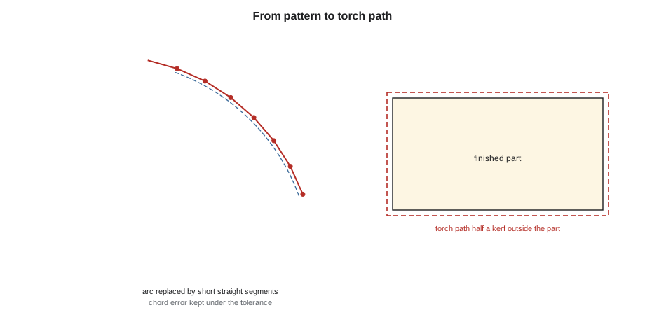
Kerf compensation
A plasma or oxyfuel cut removes a strip of metal, the kerf, a few millimeters wide. If the torch runs along the part's outline, the part comes out short by half a kerf on every edge. The torch path must be offset to the waste side by half the kerf: outside the part on its outer edges and inside any hole. Most CNC controllers do this automatically when told the kerf width and which side is the part, but the file must say which side is which, and the kerf width must match the process, the plate thickness and the consumables. For 3/8 in plate on Ironbridge's plasma table, the kerf is about 3/32 in.
On a cone piece, the offset makes the outer arc's radius half a kerf larger and the inner arc's radius half a kerf smaller, and moves the straight edges outward. Kiera's code builds the torch path that way, with the kerf allowance in the radii, so that the cut part's edges fall exactly on the pattern. The seam allowance for welding, from lesson 3, is a separate thing and is built into the pattern itself before the kerf is applied.
Kiera's file
Kiera runs the code for one hopper piece: outer radius 93.3 in, inner 23.3 in, sector angle 61.7 degrees, with the kerf and tolerance above. It prints the number of segments on each arc, a few of the outline's points in the comma-separated format the shop's software accepts, and the piece's overall envelope.
# Pattern points for the CNC table: a truncated cone sector with kerf allowance (US units)
import math
from math import gcd
MODE = "in"

def frac(x, den=16):
    sign = "-" if x < 0 else ""
    n = round(abs(x) * den); whole, rem = divmod(n, den)
    if rem == 0:
        return f"{sign}{whole} in"
    g = gcd(rem, den)
    return f"{sign}{whole} {rem // g}/{den // g} in" if whole else f"{sign}{rem // g}/{den // g} in"

def show(x):
    x = 0.0 if abs(x) < 1e-6 else x
    return f"{x:,.0f} mm" if MODE == "mm" else frac(x)
Lb, Ls, ang = 93.3, 23.3, 61.7   # outer and inner pattern radii, sector angle in degrees
kerf = 0.094                     # plasma kerf width
tol = 0.02                       # largest allowed chord error on the arcs
def segs(R):
    return math.ceil(math.radians(ang) / (2 * math.acos(1 - tol / R)))
no, ni = segs(Lb + kerf / 2), segs(Ls - kerf / 2)
print("segments on the outer arc", no, "and inner arc", ni)
ro, ri = Lb + kerf / 2, Ls - kerf / 2     # torch path sits half a kerf outside the part
pts = [(ro * math.cos(math.radians(ang * k / no)), ro * math.sin(math.radians(ang * k / no))) for k in range(no + 1)]
pts += [(ri * math.cos(math.radians(ang * (ni - k) / ni)), ri * math.sin(math.radians(ang * (ni - k) / ni))) for k in range(ni + 1)]
print("x,y")
for x, y in pts[:4] + pts[-3:]:
    print(f"{x:.3f},{y:.3f}")
print(f"... {len(pts)} points in the closed outline")
xs, ys = [p[0] for p in pts], [p[1] for p in pts]
print("part envelope", show(max(xs) - min(xs)), "by", show(max(ys) - min(ys)))segments on the outer arc 27 and inner arc 13 x,y 93.347,0.000 93.273,3.722 93.050,7.438 92.680,11.143 22.935,3.835 23.173,1.924 23.253,0.000 ... 42 points in the closed outline part envelope 82 5/16 in by 82 3/16 in
The envelope tells her the smallest rectangle of plate the piece fits in, about 82 5/16 by 82 3/16 in. The shop's 96 in wide plate will take one piece across its width, and three pieces can be nested along a 240 in plate by turning every other piece end for end, so that the curved edges nest into each other. Four hoppers need twelve pieces: four plates.
Nesting and plate use
Nesting is arranging parts on a plate to use as much of it as possible. Cone pieces nest well when alternate pieces are turned, because the outer arc of one fits near the inner arc of the next. Gores nest heel to throat, as in lesson 2. Small parts, such as nozzle reinforcing pads and clips, are nested in the waste between large parts. Nesting software does this automatically, but the boilermaker checks the result for three things: that every part's rolling direction is right if the drawing specifies one; that the heat number can be transferred to every part, which means a part must not straddle two plates; and that the parts are far enough apart for the torch and the plate's heat distortion.
Heat number transfer is a quality requirement on pressure work. Before a plate is cut, its heat number and material identification are transferred to every part that will come from it, with paint marker or low-stress stamps, so that after cutting each part can still be traced to its material certificate. Harjit witnesses the transfer on V-414's plates. On the hopper, a non-code part, the shop still marks each piece with its job and part number.
Checking the file before it cuts
Joanne's check of a CNC file has four steps. First, the key dimensions of each part are measured in the drafting program and compared with the hand calculation: the pattern radii, the sector angle, the chord across each end and the straight edge length. Second, the kerf side and width are checked in the cutting program's settings. Third, the cutting program's simulation is run to see the cut order, the lead-ins and lead-outs, which should start in the waste, not on the part edge, and the order of cuts, which should cut small internal features before outer edges so the part does not shift. Fourth, the first part cut is measured before the rest of the nest runs. Kiera's first hopper piece measures within 1/32 in on both radii and both straight edges, and Joanne releases the rest.
Cut quality and bevels
Plasma and oxyfuel cuts are not perfectly square. A plasma cut usually leaves a slight bevel, a few degrees, with one side of the cut squarer than the other, depending on the direction of travel and the gas swirl. Shops cut parts in the direction that puts the squarer side on the part and the beveled side on the waste. Oxyfuel cuts are squarer on thick plate but leave a heavier heat-affected edge. Where a part needs a weld bevel, many CNC tables can cut it with a tilting bevel head as part of the same program, saving a separate grinding or beveling step. On the hopper pieces, the seam bevels are cut by the bevel head, and Kiera adds the bevel angle and root face to her check sheet for the first part.
The first piece also tells Joanne about the plate's condition. A plate that was stressed at the mill can move as it is cut, closing or opening the kerf near the end of a long cut. If the first piece measures well at its start and badly at its finish, the nest is changed so that the long cuts are made last, with the part held by small uncut tabs until the end.
Common mistakes
MistakeUsing a template with no markings.
InsteadMark every template with job, part, thickness, diameter basis, allowances, lines and initials; scrap unmarked ones.
MistakeTrusting pattern software without a hand check.
InsteadCheck the key dimensions of every software pattern against a hand calculation.
MistakeRunning the torch along the part outline.
InsteadOffset the torch path by half the kerf to the waste side.
MistakeChoosing a very coarse segment tolerance on rolled parts.
InsteadKeep chord error well under the cut accuracy, about 0.02 in for plate parts.
MistakeNesting a part across two plates or losing its heat number.
InsteadKeep each part on one plate and transfer the heat number before cutting.
Summary and key terms
- Templates are made once, accurately, from durable material, and marked with everything needed to use them correctly.
- Patterns become CNC files as lines and arcs or lists of points; software patterns are checked by hand calculation.
- Arcs replaced by segments have a chord error R(1 − cos(Δ ÷ 2)); the segment count follows from the tolerance.
- The torch path is offset by half the kerf to the waste side; seam allowances are built into the pattern separately.
- Nesting saves plate, but must respect rolling direction, heat number transfer and spacing.
- Files are checked by dimensions, kerf settings, simulation and a first-part measurement before the nest runs.
- Template
- A durable pattern used to mark many parts.
- Kerf
- The width of metal removed by a cut.
- Kerf compensation
- Offsetting the torch path by half the kerf so the part comes out to size.
- Chord error
- The greatest distance between an arc and a straight segment replacing it.
- Nesting
- Arranging parts on a plate to use as much of it as possible.
- Lead-in
- The short cut from the waste into the part outline where the torch starts.
Practice problems
Work each problem on paper first, then reveal the answer to check.
What is the chord error of a segment spanning 2 degrees on an arc of radius 80 in?
Show answer
R(1 − cos 1°) = 80 × 0.000152 = 0.012 in.
Which way is the torch path offset for a hole in a part?
Show answer
Inside the hole, to the waste side, by half the kerf.
Why are alternate cone pieces turned end for end in a nest?
Show answer
So the outer arc of one fits near the inner arc of the next and less plate is wasted.
Why is the first part of a nest measured before the rest is cut?
Show answer
To catch any error in the file or the settings before it is repeated on every part.
Lesson quiz · 5 questions
Score 60% or more to complete this lesson.
Create a free account to save your progress, take quizzes and earn a certificate.