
BLR-210 · Lesson 12 of 12 · 19 min
Capstone: replacing a section of waterwall tube
This capstone goes back to Riverbend Unit 2 and follows the waterwall repair on the left sidewall from the leak to the signed record. Every step draws on a lesson in this course. Kiera has been on the job from the first day, and on the last day Rosa asks her to walk Grant Mahler, the authorized inspector, through the traveler, joint by joint, before he signs. What follows is what she tells him.
The failure and the plan
The leak was in tube 47, about 60 ft above the furnace floor, at the toe of a membrane fillet next to a buckstay clip. The escaping steam cut a groove in tube 48. Peg's ultrasonic thickness readings set the extent of the damage, and the repair package Harjit assembled called for replacing 4 ft of tubes 47 and 48 as a two-tube section with its center bar, made in Ironbridge's shop. The package held the repair drawing, the WPSs for the tube butt welds, window welds, membrane fillets and pad weld, the WPQs of the welders and the continuity log check, the tube material and its test report, the examination plan, the hold points, and the pressure test. Peg accepted it for Riverbend and Grant accepted it as the inspector, before the first cut.
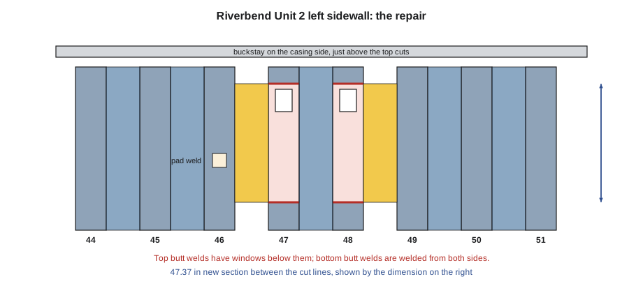
Cutting out
The crew split the membrane on both sides of the section with a 45-ampere plasma torch and a drag shield, with a shield plate behind the bar to protect the opened casing side, stopping 1 in past the tube cut lines. The section was rigged on a chain fall, freed with rough reciprocating saw cuts inside the final lines, lowered, and sent to Peg as evidence. Every tube end that stayed was plugged, and every plug was written on the traveler. The final cuts were made square on the marked lines, the bottom ones with a band saw and the top ones, under the buckstay, with a clamshell cutter. No torch touched a tube.
End preparation and fit-up
Each of the four tube ends in the wall was faced and beveled to 37.5 degrees with a 1/16 in land by a mandrel-type end prep machine, cleaned to bright metal on the bevel, outside and bore, and checked with a bevel gauge, a square and a wall gauge. Kiera measured the prepared openings on both tubes, worked out the cut length for the new section, and the shop crew trimmed and beveled it on the scaffold. Before the section went in, two windows were cut in the front of the new tubes just below the top joints, where the buckstay would block the casing side, and the window pieces were marked and kept.
At fit-up, the section was clamped with tube clamps, not dogs, because Riverbend does not allow dogs on pressure tubes. The first readings found two joints out of tolerance: a gap over the maximum at 6 o'clock on tube 48's bottom joint, and high-low over the limit at 12 o'clock on tube 47's top joint. Both were corrected by adjusting the clamps and, on tube 47, rotating the new tube to match the old tube's ovality. The joints were tacked by Marcel to the WPS, the tacks feathered, the readings retaken and recorded, and the plugs removed and checked off. Harjit and Peg released the fit-up at the hold point.
Welding the tubes
Marcel welded the furnace side of each butt joint: a GTAW root, a GTAW hot pass, and SMAW fill and cap in stacked stringers, with starts staggered and tapered and every pass cleaned. On the bottom joints, Dale welded the back quarter of the root and the passes behind it from the outside scaffold through the opened casing. On the top joints, Marcel welded the back of the root through each window from inside the tube, then fitted and welded the window piece back in with full penetration round its edges. Kiera checked the preheat before each joint and the interpass before each pass, kept the electrodes in the oven, timed passes for heat input, and recorded the welder, the filler heat numbers and the readings on the traveler.
The completed root of the first joint was a hold point; Peg looked at the inside bead with a borescope through the open top end before the section was closed, and released it. The WPS for these P-No. 1 tubes at this wall thickness required no postweld heat treatment.
Examination and one repair
Annika radiographed all four butt welds, with the windows, on the night shift. Three were accepted. Tube 47's top joint showed incomplete fusion at the edge of the window's inside weld, where the root welded through the window met the front half, over a short length. It was rejected, as any planar flaw would be. Marcel ground out the indication from the outside, Kiera ran penetrant on the cavity to confirm it was gone, Marcel rewelded it to the WPS, and Annika radiographed it again the next night. Repair 47T-R1 was accepted, the first repair on that area, inside Riverbend's limit of two.
With the butt welds accepted, the membrane was closed. New bars were cut to fit, tacked, and fillet-welded to the old and new tubes on both faces in short lengths, alternating sides and working from the middle outward, with the craters filled and the toes ground smooth near the buckstay clip. The fillets got visual and magnetic particle examination. On tube 46, the small steam-cut spot was ground, examined, built up with a pad weld to the WPS, ground to contour, and checked by ultrasonic thickness and magnetic particle testing, as Peg and Grant had accepted.
The pressure test
The last hold point is the hydrostatic test. The repair plan that Grant accepted called for testing the boiler at its MAWP, with the safety valves gagged, and the crew checked the plan against the limits before filling. A repair test must not exceed the code's new-construction test of 1.5 times the MAWP; the test gauge must have a range suited to the test pressure, roughly twice it and within the limits the procedure sets; and the water must be in the temperature range the procedure gives, warm enough that the steel is not brittle and cool enough for the inspectors to touch the welds.
# Capstone: hydrostatic test and repair record for the waterwall section (US units)
mawp = 1_700
ceiling = 1.5 * mawp                     # the code's new-construction test; no repair test goes above it
test = 1_700                            # test pressure in the repair plan the inspector accepted
gauge = 4_000                          # full scale of the test gauge
print(f"MAWP {mawp:,} psi, plan test {test:,} psi, ceiling {ceiling:,.0f} psi",
      "OK" if test <= ceiling else "TOO HIGH")
ratio = gauge / test
print(f"gauge {gauge:,} psi is {ratio:.1f} times the test pressure",
      "OK" if 1.5 <= ratio <= 4 else "choose another gauge")
water = 80
print("water temperature", water, "°F", "OK" if 70 <= water <= 120 else "adjust before filling")

record = [
    ("tube 47 bottom butt", "GTAW/SMAW", "RT accept"),
    ("tube 48 bottom butt", "GTAW/SMAW", "RT accept"),
    ("tube 47 top butt + window", "GTAW/SMAW", "RT reject, repaired 47T-R1, RT accept"),
    ("tube 48 top butt + window", "GTAW/SMAW", "RT accept"),
    ("membrane bars", "SMAW", "VT and MT accept"),
    ("tube 46 weld buildup", "SMAW", "UT and MT accept"),
]
print("\nrepair record, Riverbend Unit 2 left sidewall, tubes 47 and 48")
for part, proc, nde in record:
    print(f"  {part:27} {proc:10} {nde}")
print("  PWHT: not required for P-No. 1 tube at this wall in the WPS")
print(f" hydrostatic test at {test:,} psi: held, no leaks, inspector signed")MAWP 1,700 psi, plan test 1,700 psi, ceiling 2,550 psi OK gauge 4,000 psi is 2.4 times the test pressure OK water temperature 80 °F OK repair record, Riverbend Unit 2 left sidewall, tubes 47 and 48 tube 47 bottom butt GTAW/SMAW RT accept tube 48 bottom butt GTAW/SMAW RT accept tube 47 top butt + window GTAW/SMAW RT reject, repaired 47T-R1, RT accept tube 48 top butt + window GTAW/SMAW RT accept membrane bars SMAW VT and MT accept tube 46 weld buildup SMAW UT and MT accept PWHT: not required for P-No. 1 tube at this wall in the WPS hydrostatic test at 1,700 psi: held, no leaks, inspector signed
The test pressure of 1,700 psi is well below the 2,550 psi ceiling, the gauge is about 2.4 times the test pressure, and the water is at 80 °F. The boiler was filled, vented, brought up to the test pressure in steps, and held. Grant, Peg and Harjit walked the scaffold with flashlights, looking at every new weld on both faces. There were no leaks and no weeping. The pressure was let down, the boiler drained to the operating level, and the gags removed.
The record
When Kiera finishes, Grant reads the traveler and the radiography reports, checks that each weld has its welder, WPS, filler, readings and examinations, and signs the repair. The record goes into Riverbend's boiler file with the R-1 repair report that Ironbridge prepares under its R certificate and the inspector signs, and copies go to the state as its rules require, with the failed section's examination report from Peg and her recommendation to redesign the buckstay clip at the next planned outage. Unit 2 goes back on line the following morning, eleven days after the trip.
| Step | What was done | Lesson |
|---|---|---|
| Plan and qualify | Repair package; WPSs and WPQs; continuity check | 1, 9 |
| Cut out | Plasma membrane splits, rough saw cuts, final square cuts, plugs recorded | 3 |
| Prepare ends | Machine bevels, cleaning, end checks, new section cut to length | 7 |
| Fit up | Clamps, gap and high-low at four points, tacks, recheck | 7 |
| Weld | GTAW root and hot pass, SMAW fill and cap, windows on the top joints | 8, 9 |
| Heat control | Preheat and interpass checks; no PWHT for this P-No. 1 tube | 10 |
| Examine and repair | RT of all butts, one rejection repaired and re-radiographed | 11 |
| Close the wall | Membrane fillets both faces, MT; pad weld on tube 46 with UT | 8, 9 |
| Test and record | Hydrostatic test within limits, traveler and reports signed | 12 |
What Kiera learned
Grant asks Kiera what she would do differently. She says the high-low on tube 47 would have been caught sooner if she had checked the new tube's ovality at the top end before it was fitted, and that the window weld rejection shows the inside weld through a window needs a mirror check before the window goes back in. Marcel writes both into his notebook. Rosa's note on Kiera's apprenticeship record is short: cut-out, end prep, fit-up and traveler to pressure standard, ready to start tube welding practice for her pressure test. In BLR-220, the work moves on to how boilers, heat exchangers and pressure vessels are built and assembled, and in BLR-320 to the codes behind the stamps on them.
Worked problem
Checking the test plan
A boiler has an MAWP of 1,700 psi. The repair plan calls for a test at the MAWP, using a gauge with a full scale of 4,000 psi. Does the plan stay under the 1.5 times MAWP ceiling, and is the gauge range reasonable?
Show solution
- Ceiling: 1.5 × 1,700 = 2,550 psi; the test at 1,700 psi is below it.
- Gauge ratio: 4,000 ÷ 1,700 = 2.4, between 1.5 and 4 and close to the preferred 2.
Answer: Yes on both counts. The plan is within the ceiling and the gauge suits the test pressure.
Handing the boiler back
Before Unit 2 is returned to the operators, the crew finishes the jobs that do not show on the traveler. Every tool, rag, plug, scrap of tube and electrode stub is removed from the furnace and the casing side, and Kiera and Dale make a final walk-down of the scaffold with a checklist. The casing and insulation are closed and the lagging replaced. The scaffold comes down only after the operators confirm they do not need access for the start-up. And the work permits are signed off, so the operators know the hot work, the confined space entry and the isolation are finished. Tyrone Beaulieu, the operator who issued the permits, walks the job with Rosa before he removes the locks.
Common mistakes
MistakeStarting work before the package is accepted.
InsteadGet the owner's and inspector's acceptance first.
MistakeMeasuring the new section before the wall ends are prepared.
InsteadPrepare the ends, then measure the opening and cut.
MistakeClosing a window without checking the inside weld.
InsteadCheck the inside weld with a mirror or borescope before refitting the window.
MistakeClosing the membrane before the butt welds are accepted.
InsteadRadiograph and accept the butt welds first.
MistakeTesting above the code ceiling or with a gauge that is too small.
InsteadCheck the test pressure and gauge range against the limits before filling.
Summary and key terms
- A code tube repair is planned, accepted, cut out, prepared, fitted, welded, examined, tested and recorded in that order.
- Membrane is split with plasma; tubes are cut mechanically and plugged; the section is freed before final cuts.
- Machine bevels, clean ends and fit-up checks at four points prevent most weld defects.
- Windows give access to the back of joints that cannot be reached; their inside welds need checking.
- Every butt weld is radiographed; rejected welds are excavated, confirmed clean, rewelded and re-examined.
- The hydrostatic test, within the ceiling and with a suitable gauge, is the last hold point before the record is signed.
- Repair record
- The signed record of a code repair, with joints, welders, procedures, examinations and the test.
- Gagging
- Holding a safety valve closed during a hydrostatic test above its set pressure.
- Borescope
- An optical instrument for looking inside a tube or other closed space.
- MAWP
- Maximum allowable working pressure: the highest pressure the boiler is permitted to operate at.
- Hydrostatic test
- A pressure test with water, used to prove a pressure part is tight and sound.
- Hold point release
- The inspector's sign-off that lets work continue past a hold point.
Practice problems
Work each problem on paper first, then reveal the answer to check.
A boiler's MAWP is 1,300 psi. What is the ceiling for a repair test under the rule in this lesson?
Show answer
1.5 × 1,300 = 1,950 psi.
A test is at 1,300 psi and the gauge is 1,500 psi full scale. Is the gauge suitable?
Show answer
No; the ratio is 1.2, below 1.5. Use a gauge of about 2,500 to 3,000 psi.
Why was the failed section sent to Peg?
Show answer
It is evidence of the cause of the leak, which decides how to prevent the next one.
Name the four kinds of weld in the Riverbend repair.
Show answer
Tube butt welds, window welds, membrane fillets and a pad weld.
Lesson quiz · 5 questions
Score 60% or more to complete this lesson.
Create a free account to save your progress, take quizzes and earn a certificate.