
BAS-420 · Lesson 7 of 12 · 24 min
Mechanical problems that look like control problems
▶ Video coming soon A video version of this lesson is on the way.
"If you only remember one thing from this binder," Prakash said, "remember that the controls are usually the messenger." He turned to the seventh tab, which he had labeled Not ours. It held the calls that had come to Quillon as controls problems and turned out to be mechanical: the coupling slipping on room 108's reheat valve stem, the broken belts on Tilden's EF-3, the low chilled water temperature difference at Ninefield, the rooftop damper that stalled after someone added blade seals. In each case the BAS had seen the problem first, and in each case the fix was a wrench, a belt or a valve, not a program change.
This lesson covers mechanical faults that show up as control symptoms: dampers and linkages, belts and fans, filters and coils, air and dirt in hydronic systems, valves that are the wrong size or type, and plant problems such as low temperature difference. The control technician does not have to fix all of these, but has to recognize them, prove them, and hand them to the right trade with evidence.
Why mechanical faults look like control faults
A control loop can only move what it is connected to. When a valve is stuck, a coil is fouled or a belt is slipping, the loop does what loops do: it drives its output further to try to reach setpoint. The symptom the BAS reports is a control symptom, such as a temperature off setpoint, an output pinned at 100, or a loop that hunts, but the cause is in the equipment. A technician who starts retuning the loop or rewriting the sequence will make no progress, and may make things worse.
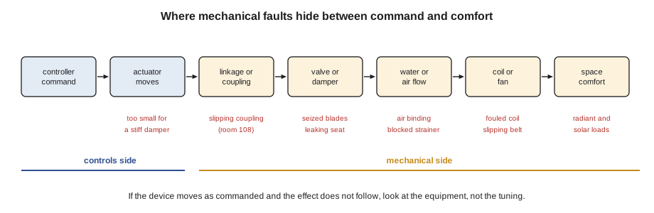
The key test is to separate the command from the result. If the controller commands a damper to 100 and the damper is at 100, the controls have done their part. If the airflow does not follow, the problem is in the ductwork, the fan or the damper blades. If the controller commands a valve open and the valve is open, but the coil does not heat, the problem is in the water: no flow, no heat at the source, air in the coil or a blocked strainer.
Dampers and linkages
Dampers fail mechanically in several ways. Blades seize on dirty or rusted bearings. Linkages loosen, so the actuator moves but the blades do not, or move only part way. Jackshafts slip in their clamps. Outdoor air dampers can freeze shut in winter when moisture collects on the blades. Seals and blade edges wear, so a closed damper leaks.
The test is to watch the damper itself while the actuator strokes, not the actuator's position indicator. If you can see the blades, look. If you cannot, feel the airflow, measure the temperature downstream, or watch a related point such as the mixed air temperature when the outdoor air damper is commanded open on a cold day. An outdoor air damper that is really opening should pull the mixed air temperature down within a minute or two.
A damper can also be too stiff for its actuator. At Ninefield in October, RTU-2's outdoor air damper had had blade seals added in 2015 without the actuator being upsized. The seals made the damper much harder to turn, and the actuator stalled part way. The BAS showed an economizer that never reached its command. The actuator was not faulty; it was too small for the job it had been given. The fix was a larger spring-return actuator, 90 in·lb, sized for the sealed damper.
Belts, fans and pumps
Fan belts stretch and wear. A slipping belt turns the fan slower than the motor, so the fan delivers less air than its speed command suggests. A broken belt stops the fan completely while the motor spins. From the BAS, both look like control problems: low static pressure, a drive running at full speed without reaching setpoint, or zones that cannot get enough air.
Motor current and drive power are the best indirect evidence. A fan's power falls roughly with the cube of its speed (the fan affinity laws), so the power at any speed can be predicted from a known point. A fan drawing much less power than expected at a given speed is moving less air: a slipping or broken belt, a closed damper somewhere, or a fan wheel loose on its shaft.
Worked problem
Checking a fan's power against the affinity laws
In August, a Ninefield penthouse supply fan drew 13.0 kW at 60 Hz. In November it drew 5.9 kW at 45 Hz. Does the November reading suggest a belt problem? What would a reading of 3.0 kW at 45 Hz suggest?
Show solution
- Speed ratio: 45 ÷ 60 = 0.75.
- Expected power from the cube law: 13.0 × 0.75 × 0.75 × 0.75 = 13.0 × 0.42 = 5.5 kW.
- The measured 5.9 kW is close to the prediction (the affinity laws are only approximate on a real system with a static pressure setpoint, which tends to make real power a little higher than the cube law says).
- A reading of 3.0 kW at 45 Hz would be about 0.55 of the expected 5.5 kW, which suggests the fan is moving much less air than it should.
Answer: The November reading is consistent with a healthy fan. A reading near 3 kW would point to a slipping or broken belt, a loose wheel or a blocked air path, and is the basis of the belt-loss rule added to Ninefield's fault detection.
Tilden's EF-3 is the cautionary case. Its belts broke and its status stayed on, because the current switch could not tell the motor's no-load current from its running current. For a fan where airflow matters, a differential pressure or airflow switch proves the thing that matters. For a fan on a drive, the drive's power or current reading over the network, compared with what is expected at that speed, is a cheap and powerful check.
Pumps have their own mechanical faults: worn impellers, closed or partly closed isolation valves, blocked strainers, a check valve stuck open so that a standby pump circulates backwards through the running one. A pump running at full speed without reaching its differential pressure setpoint, or a differential pressure that does not change when the pump speed changes, points to a mechanical problem in the circuit.
Filters, coils and heat transfer
A loaded filter reduces airflow. On a VAV system with static pressure control, the fan speeds up to compensate, so the symptom is higher fan speed and power rather than lost airflow, until the fan runs out of speed. On a constant volume system, airflow simply falls. Filter differential pressure switches and transmitters are meant to catch this, but only if their tubes are on the right ports, as the Ninefield filter switch with its tubes swapped showed. On the Tilden walk on November 12, AHU-1's final filters were noted as near their alarm point, which was put in the report as an item for the college.
Coils foul on the air side with dust and on the water side with scale and sludge. A fouled coil transfers less heat, so a valve has to open further to do the same job, and the loop's output rises over months for the same load. A trend of valve position against load, compared year on year, can show it. The temperature difference across a fouled water coil also falls, which matters for the plant.
Air in a hydronic system is a classic look-alike. Air collects at high points, often in the coils of top-floor units or in fan coils in stair halls. An air-bound coil gets little or no water flow even with its valve wide open, so the space is cold while the controls are doing everything right. The clues are a gurgling sound, a cold coil with an open valve and hot supply water, and a problem that is worst on the highest floors. The fix is to vent the air and find out why it is getting in: a low fill pressure, a leak drawing air in, or a failed air separator.
Valves: authority, size and type
A control valve has to be the right size and type for the loop to work. An oversized valve does almost all of its work in the first few points of its stroke, so the loop sees a huge change in output for a small change in command and tends to hunt. An undersized valve cannot pass enough water, so the loop saturates at 100. Both look like tuning problems.
Valve authority describes how much of the circuit's pressure drop is across the valve when it is fully open. A valve with low authority has little control over the flow until it is nearly closed, which also makes loops hunt. Designers usually aim for an authority of about 0.5 (a typical design target).
Worked problem
Valve authority
A coil circuit has a pressure drop across the fully open valve of 6 psi and a drop across the coil, piping and fittings of 7.5 psi at design flow. What is the valve's authority?
Show solution
- Authority = valve drop ÷ (valve drop + rest of circuit drop).
- 6 ÷ (6 + 7.5) = 6 ÷ 13.5 = 0.44.
- That is close to the typical target of about 0.5, so the valve should control well across its stroke.
Answer: About 0.44, close to the valve schedule Declan and Sophie prepared for Ninefield's three-way to two-way conversion, where the selected valves gave an authority of about 0.45.
Valve type matters for the plant as well as for the loop. A three-way valve bypasses water around the coil when it closes, so the flow through the system stays roughly constant and the return water comes back colder (for chilled water) than it should. That is one of the main causes of low temperature difference.
Low temperature difference in a chilled water plant
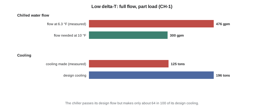
Ninefield's chilled water plant has been running at a temperature difference of about 6.3 °F across the chillers, against a design of 10 °F. The controls see the symptom first: more flow and more pumping for the same cooling, and chillers that cannot be loaded fully. But the causes are mostly mechanical: three-way valves on the oldest air handlers, coils that are fouled or piped wrongly, valves that leak through, and coils that are overpumped because they have no balancing or pressure-independent valves.
Worked problem
What low temperature difference costs in flow
In August, chiller CH-1 was making about 125 tons of cooling at a temperature difference of 6.3 °F. What chilled water flow was it passing, and what flow would the same cooling need at the design difference of 10 °F?
Show solution
- Flow in gpm = 24 × tons ÷ temperature difference in °F.
- At 6.3 °F: 24 × 125 ÷ 6.3 = 476 gpm, which matches the 475 gpm measured in August.
- At 10 °F: 24 × 125 ÷ 10 = 300 gpm.
- The chiller is passing about 476 gpm, close to its design flow, while making only about 64 in 100 of its design capacity of about 196 tons.
Answer: About 476 gpm at 6.3 °F against 300 gpm at 10 °F. The chiller runs out of flow long before it runs out of capacity, which is why low temperature difference is a plant problem and not a tuning problem.
The controls technician's job here is to prove it with trends and readings, not to fix it with programming. A list of air handlers with their valve types, valve positions, coil entering and leaving water temperatures and airflow is the evidence the mechanical engineer needs. At Ninefield, that evidence became part of the spring 2027 retro-commissioning plan: two-way valves on the oldest air handlers and a chilled water meter that reads correctly.
Proving a mechanical fault and handing it over
When the evidence points to a mechanical fault, the controls technician's job changes. It is no longer to fix the fault but to prove it clearly enough that the right person can fix it without repeating the investigation.
- Show that the controls are doing their part: the command, the device position and the signal at the terminal.
- Show the mechanical evidence: a trend of the effect not following the command, a measured temperature or pressure, a photograph of a loose linkage, a current or power reading.
- Say what you think the cause is and how sure you are, and what test would confirm it.
- Say who needs to fix it: the mechanical contractor, the owner's maintenance staff, the balancing firm, the equipment manufacturer.
- Leave the system safe and as comfortable as possible in the meantime, and record any temporary measure.
Do not adjust the controls to hide a mechanical fault unless the owner agrees and it is recorded. Raising a static pressure setpoint to cover a loaded filter, or lowering a supply water temperature to cover a fouled coil, makes the symptom go away and leaves a building that wastes energy and fails without warning later.
Common mistakes
MistakeRetuning a loop that cannot reach setpoint without checking that the equipment can deliver.
InsteadCheck that the device moves, the medium flows and the source is available before touching the tuning.
MistakeTrusting the actuator position indicator as proof the damper or valve moved.
InsteadWatch the blades or stem, check for slipping couplings, and look at the effect downstream.
MistakeTreating low chilled water temperature difference as a chiller control problem.
InsteadIt is mostly caused by valves and coils in the system; document them for the mechanical engineer.
MistakeRaising a setpoint to cover a mechanical fault.
InsteadProve the fault, hand it to the right trade with evidence, and record any temporary measure.
Summary and key terms
- Mechanical faults appear as control symptoms because loops drive harder to make up for equipment that cannot deliver.
- Separate the command from the result: if the device moves as commanded and the effect does not follow, look at the equipment.
- Dampers seize, linkages slip and actuators can be too small for a sealed damper; watch the blades, not the indicator.
- Fan power against the affinity laws reveals slipping or broken belts; current switches alone cannot.
- Fouled filters and coils, air-bound coils and blocked strainers show as slowly rising outputs, cold coils with open valves, and loops that saturate.
- Valve size, authority and type affect control and the plant; three-way valves are a main cause of low temperature difference.
- Prove mechanical faults with evidence and hand them to the right trade; do not hide them with setpoint changes.
- Affinity laws
- Approximate relationships for fans and pumps: flow varies with speed, pressure with speed squared and power with speed cubed.
- Air binding
- Air trapped in a coil or high point that blocks water flow.
- Valve authority
- The fraction of a circuit's total pressure drop that is across the fully open control valve.
- Low delta-T
- A chilled or hot water temperature difference well below design, which raises flow and pumping for the same load.
- Three-way valve
- A valve that diverts water around a coil instead of throttling it, keeping system flow roughly constant.
Practice problems
Work each problem on paper first, then reveal the answer to check.
A heating valve is commanded and measured at 100, hot water supply is at setpoint, and the space stays cold. The top-floor fan coils are worst. What do you suspect?
Show answer
Air binding in the coils or piping at high points; listen for gurgling, check whether the coil is cold, and check the system fill pressure and air separator.
A VAV air handler fan has been slowly running faster for the same airflow over several months. What mechanical cause is likely?
Show answer
Filters loading (or a fouled coil) adding resistance; check filter pressure drop and condition.
Why is a fixed temperature difference not something the BAS can program its way out of?
Show answer
Because it is set by how the coils, valves and piping move heat and water; the controls can only measure it and help prove the causes.
Lesson quiz · 5 questions
Score 60% or more to complete this lesson.
Create a free account to save your progress, take quizzes and earn a certificate.