
BAS-420 · Lesson 12 of 12 · 21 min
Troubleshooting case studies
▶ Video coming soon A video version of this lesson is on the way.
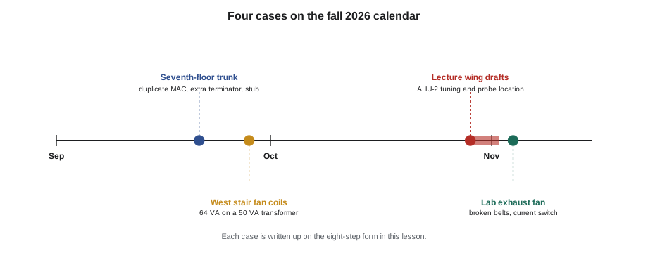
The last tab in Prakash's trouble file is not a tab of faults but a tab of blank forms: the eight-step page from the front of the binder, printed with space under each step. "Pick four calls from this fall," he told Callie, "and write each one up on this form, step by step, as if you were teaching it. Then tell me what they have in common." She chose the lecture wing drafts, the seventh-floor trunk, the west stair fan coils and the lab exhaust fan with the broken belts. This lesson is her write-up, with Prakash's comments, followed by a practice case for you to work through.
Each case is set out with the eight steps from lesson 1. Read them for the method rather than the details: what the symptom statement was, which data settled the question, where the chain was split, and how the fix was verified.
Case 1: the lecture wing drafts
| Step | Tilden AHU-2, Thursday October 29 to Monday November 2 |
|---|---|
| 1. Symptom | Lecture wing occupants felt cold drafts. A fast trend showed AHU-2 discharge air hunting 62.6 to 66.2 °F with a 96-second period and the heating valve swinging 20 to 40. |
| 2. Data | The 10-second trend set up in October for loop work; the 5-minute trend for Gus had hidden it. The change log showed a September tuning change: gain 2 to 4.4 per °F, integral 90 to 30 s, for a faster warm-up. |
| 3. Hypotheses | Aggressive tuning; a sticky valve; sensor location or noise; interaction with another loop. |
| 4. Least invasive tests | Trend shape: smooth swings in both output and temperature, not a sawtooth, so tuning more likely than stiction. Inspection: the probe sat 2 ft after the coil, in stratified air. |
| 5. Split | The valve followed its command smoothly when watched, ruling out the device. The oscillation was in the loop and its measurement. |
| 6. Fix | Friday October 30, 7:00: probe moved downstream of the supply fan; step test (30 to 40, +7.2 °F, dead time 20 s, time constant 60 s); lambda tuning to 1.04 per °F, integral 60 s. |
| 7. Verify | Monday November 2: a full occupied period within ±0.4 °F. |
| 8. Document | Old and new settings and the step test in the change log; an averaging sensor and a return air damper actuator added to the AHU-2 replacement file; start schedule review with Gus and Nell. |
Prakash's comment: "Two causes, as usual. If you had only retuned, the stratified air would have kept nudging the loop. If you had only moved the probe, the tuning was still four times too hot. And the September change was somebody fixing a different complaint, the slow warm-up. When you retune, write down why, so the next person does not undo it."
Case 2: the seventh-floor trunk
| Step | Ninefield Tower seventh floor, Monday September 21 |
|---|---|
| 1. Symptom | About half the floor's VAV controllers dropping offline and back every few minutes, since a tenant fit-out in July. |
| 2. Data | Front-end device list and offline history; the fit-out had replaced VAV-7-14 and added a new box on a branch. |
| 3. Hypotheses | Duplicate address; wrong termination; a stub; noise; a failing transceiver; a router problem. |
| 4. Least invasive tests | Device list: VAV-7-14 at MAC 3, the same as VAV-7-03. Trunk resistance with power off: 41 Ω, which means three terminators. Inspection: a 40 ft stub to the new box. |
| 5. Split | Not needed in the end; the resistance reading and device list pointed straight at the replaced controller. A protocol capture confirmed two replies to every token passed to MAC 3. |
| 6. Fix | New box controller set to MAC 23; replacement controller's terminator switched off; stub rewired into the daisy chain. |
| 7. Verify | Trunk resistance 61 Ω; 23 controllers stable on the front end. |
| 8. Document | Addresses recorded against Ninefield's numbering plan; a note to Ilona about contractor-replaced controllers needing Quillon's settings before connection. |
Prakash's comment: "Three faults at once, each of which on its own might only have caused the odd error. That is why the symptoms were confusing. The resistance reading cost one minute and told us more than an hour of watching the front end. And ask what changed: the answer was the fit-out, two months before."
Case 3: the west stair fan coils
| Step | Tilden Hall west stair, Monday September 28 |
|---|---|
| 1. Symptom | The four west stair fan coil controllers dropping offline one at a time, mostly on cold mornings, and recovering on their own. |
| 2. Data | Offline times clustered when the actuators drove at morning start. Service history: the spring-return actuators were replaced in 2021, and a 2023 entry recorded a swapped hot and common that blew an actuator fuse. |
| 3. Hypotheses | Transformer overload; voltage drop to the far controller; loose terminals; polarity; network fault. |
| 4. Least invasive tests | VA count from data sheets: 4 × 6 + 4 × 10 = 64 VA on a 50 VA transformer. Measurement with all actuators driving: 25.9 V falling to 21.3 V at the transformer and 19.8 V at the top controller. |
| 5. Split | Measuring at the transformer and at the top controller at the same moment separated transformer sag from wire drop: most of the loss was at the transformer. |
| 6. Fix | Harcastle's electrician fitted a 100 VA transformer early on Tuesday September 29. |
| 7. Verify | Retest with all actuators driving: 24.6 V at the transformer, 23.4 V at the top controller. No further dropouts. |
| 8. Document | Label: 64 VA connected, 100 VA rated. Backups of the four controllers taken the same afternoon, and a change log started. |
Worked problem
How close the top controller came to its limit
Many 24 VAC controllers are rated for 24 V plus or minus 20 in 100 (a typical tolerance). What is the minimum voltage on that basis, and how did the west stair readings compare before and after the fix?
Show solution
- Minimum: 24 × (1 − 0.20) = 24 × 0.80 = 19.2 V.
- Before: 19.8 V at the top controller, only 0.6 V above the typical minimum, with the actuators driving. Any extra drop, such as a cold morning when all four drove fully, would take it below.
- After: 23.4 V at the top controller, 4.2 V above the minimum.
Answer: The top controller was running within about 0.6 V of a typical minimum before the fix and about 4.2 V above it after. Intermittent resets that come and go with load are what you expect from a supply running that close to its limit.
Prakash's comment: "Nothing was broken. The fault was a replacement that was better than the original in every way except its VA. Add it up, every time, and write it on the label."
Case 4: the lab exhaust fan with broken belts
| Step | Tilden Hall EF-3 (chemistry lab exhaust), Wednesday November 4 |
|---|---|
| 1. Symptom | EF-3 showed status on, but its belts were found broken; the lab exhaust had not been moving air although the BAS raised no alarm. |
| 2. Data | Status history showed EF-3 on throughout; no alarms. Motor nameplate and readings: about 14 A full load, 11.5 A running normally, 5.6 A with no belt. |
| 3. Hypotheses | The status device cannot tell a running fan from a spinning motor; status overridden; a wiring fault holding the input closed. |
| 4. Least invasive tests | Priority array and input status: no override. The current switch was a fixed-trip type whose low threshold was below the no-load current. |
| 5. Split | The input followed the switch, and the switch followed the current; the fault was the switch's threshold, not the wiring or the program. |
| 6. Fix | Belts replaced; the fixed-trip switch replaced with an adjustable split-core switch set at 8.5 A, between no-load and running current. |
| 7. Verify | Before the new belts went on, the motor was run uncoupled and status stayed off at 5.6 A; with the belts on, status made reliably at 11.5 A. |
| 8. Document | Recommendation for an airflow switch on the lab exhaust; a belt-loss check by current or power added to Quillon's fault rule list. |
Worked problem
Choosing a current switch setting
EF-3's motor draws 5.6 A with no belt and 11.5 A running normally. Where should an adjustable current switch be set so that it proves the belt is driving the fan?
Show solution
- The setting must be above the no-load current and below the normal running current.
- Midpoint: (5.6 + 11.5) ÷ 2 = 8.55 A, about 8.5 A.
- Margins: 8.5 − 5.6 = 2.9 A above no-load and 11.5 − 8.5 = 3.0 A below running.
Answer: About 8.5 A, roughly halfway, which leaves a margin either side for changes in load. Where airflow itself must be proved, as on a laboratory exhaust, an airflow or differential pressure switch is the better device.
Prakash's comment: "The BAS told the truth about the current. It just was not the question that mattered. Always ask what a status point actually proves."
What the four cases have in common
Callie's answer to Prakash's question was a short list, and it is a good summary of the course.
- In every case, the first useful data was already in the system or in the job folder: a fast trend, a device list, a service history entry, a status history.
- In every case, something had changed: a tuning change, a contractor's replacement controller, replacement actuators, or simply wear on a belt.
- Three of the four had more than one cause, or a cause plus a contributing factor. Fixing only one would have left the symptom, or brought it back.
- The decisive test was cheap: a trend shape, a resistance reading, a VA sum, a current reading. None of the cases needed a part replaced to find the fault.
- The fixes were in four different places: a program setting and a sensor location, controller configuration and wiring, a transformer, a field device. The method was the same.
- Each was verified under the conditions that caused it, and each left something behind for the next technician: settings with reasons, addresses on a plan, a label, a recommendation.
| Case | Kind of fault | Decisive evidence | Contributing factor |
|---|---|---|---|
| Lecture wing drafts | Program tuning and sensor location | Fast trend shape and change log | Probe in stratified air |
| Seventh-floor trunk | Network configuration and wiring | Trunk resistance 41 Ω and device list | Stub and extra terminator |
| West stair fan coils | Power supply | VA sum and voltage under load | Voltage drop to the top controller |
| Lab exhaust fan | Field device choice and setting | Current readings against switch threshold | Broken belts (mechanical) |
Practice case: the lobby that would not settle
Work through this case yourself on the eight-step form before reading the notes that follow. It is based on a Ninefield call from September, described in BAS-120.
The building staff at Ninefield report that the main lobby doors are hard to close and whistle on windy days, and tenants complain of drafts in the podium shops near the entrance. The BAS shows building static pressure steady at its setpoint of +0.02 in. w.c. all day. The building pressure control appears to be working normally on the front end.
- What is the symptom statement, and what changed?
- What hypotheses would you list along the chain from the building static sensor to the dampers?
- What is the least invasive test that would tell you whether the BAS reading is true?
- Where would you split the chain?
Notes. A building static reading that sits steadily at setpoint while the building clearly behaves as if it is over-pressurized suggests the measurement, not the control. The chain runs from the outdoor reference pickup and its tubing, through the transmitter, to the input, the loop and the dampers. The least invasive test is a handheld manometer reading of lobby pressure against outdoors, compared with the BAS. At Ninefield, the true lobby pressure was about +0.11 in. w.c.. Following the outdoor reference tube found it cut during a 2024 roofing repair, so the transmitter was comparing the lobby with the air in a ceiling space rather than outdoors. The fix was a new, shielded outdoor reference pickup and tube. Verification is the handheld reading and the BAS agreeing, and the doors closing normally on a windy day. Documentation would include a note to the roofing contractor's file and a check of other tubes that cross the roof.
Building your own trouble file
Prakash's binder took twenty years to fill, but Callie's has already started with these four write-ups. Every technician benefits from keeping one: a short record of each interesting call, written on the eight-step form, with the charts and photographs that told the story. Over time it becomes a library of symptoms and their causes for the buildings you look after, and a way of seeing patterns, such as one manufacturer's coupling that slips, or one contractor's habit of leaving default addresses, that no single call would show.
It is also the habit that turns experience into skill. A technician who solves a problem and moves on remembers the answer. A technician who writes down how the problem was solved remembers the method, and the method is what works on the next problem, which will look nothing like this one.
Common mistakes
MistakeReading a case study for its specific answer.
InsteadRead it for the method: symptom, data, hypotheses, cheap decisive tests, split, fix, verification, documentation.
MistakeStopping at the first cause found.
InsteadAsk whether anything else contributed; three of these four cases had a second factor.
MistakeKeeping case notes only in your head.
InsteadWrite each interesting call on the eight-step form with its evidence; patterns appear over time.
Summary and key terms
- The eight-step method worked the same way on a tuning fault, a network fault, a power fault and a field device fault.
- The first useful data was already in the system or job folder in every case.
- Something had changed before every fault; asking what changed is one of the most valuable questions.
- Most cases had a contributing factor as well as a main cause.
- The decisive tests were cheap: trend shapes, resistance and voltage readings, VA sums and current readings.
- Verification under the right conditions and documentation for the next technician closed each case.
- Keeping your own trouble file turns individual calls into a method and a library of patterns.
- Case study
- A worked account of a real problem set out step by step for learning.
- Contributing factor
- A condition that made a fault worse or more likely without being its main cause.
- Trouble file
- A technician's own record of interesting calls, written up by method with their evidence.
Practice problems
Work each problem on paper first, then reveal the answer to check.
In case 3, why did measuring at the transformer and at the top controller at the same moment matter?
Show answer
It separated transformer sag (25.9 to 21.3 V at the transformer) from voltage drop along the wiring (21.3 to 19.8 V), showing most of the loss was at the overloaded transformer.
In case 2, what single reading pointed most directly to an extra terminator?
Show answer
The trunk resistance of 41 Ω with power off, which matches three 120 Ω terminators in parallel.
In the practice case, why is a handheld manometer reading the first test rather than recalibrating the transmitter?
Show answer
It is least invasive and tells you directly whether the BAS reading is true; if it is not, you then follow the chain to find out why, which in this case was a cut reference tube.
Lesson quiz · 5 questions
Score 60% or more to complete this lesson.
Create a free account to save your progress, take quizzes and earn a certificate.