
BAS-210 · Lesson 7 of 12 · 23 min
Low voltage wiring, conduit and code requirements
▶ Video coming soon A video version of this lesson is on the way.
On the afternoon of Monday, October 5, Callie went back to Ninefield with Declan Kilbride to survey the roof for the RTU-1 job. They met Tegan Farrow, a licensed electrician from Kelso Electric, the electrical contractor Ninefield used, beside the rooftop unit. Tegan's company would bring a 120 volt circuit to the new controls panel; Quillon would do everything on the low-voltage side. The three of them walked the route the network cable would take from the penthouse supervisory controller down through the building to the podium roof, and Declan marked where the panel would mount. Most of the conversation was about who was allowed to do what, and how each part had to be installed. This lesson covers the electrical code rules that shape controls wiring.
Two codes, one idea
Electrical installations in the United States are governed by the National Electrical Code, NFPA 70, adopted by states and cities; Ohio and Columbus adopt it with local amendments. The code's idea for controls is simple: circuits whose power is limited so that they are not a shock or fire hazard can be installed with lighter methods than ordinary power circuits, provided they are kept apart from power circuits and installed with suitable cable.
These limited circuits are called Class 2 circuits. The 2023 edition of the code reorganized the material: Class 2 and Class 3 circuits are in Article 725, Class 1 circuits moved to a new Article 724, and the cables used for these and other limited circuits are in Article 722. A technician should know which edition is adopted where they work, because rule numbers and some requirements change between editions. This lesson describes the requirements in general terms; the code itself is the authority.
What makes a circuit Class 2
A circuit is Class 2 because of its power source, not because of its wire. The source must be a listed Class 2 power supply or transformer, which limits the voltage and the power the circuit can deliver even under fault. At the 24 volt level used for building controls, that limit is about 100 volt-amperes, as lesson 3 explained. Everything connected on the secondary side of that source is part of the Class 2 circuit. If anything on that circuit is fed from another source, such as a line-voltage relay contact wired into it, the circuit is no longer purely Class 2 and must be treated as the higher class.
Class 1 circuits are remote-control and signaling circuits that are not power-limited in the same way, or are limited to higher levels, and they must be installed with wiring methods closer to those for power circuits. A 120 volt circuit to a starter coil is a Class 1 circuit. Some controls panels contain both, which is why lesson 5's layout separated them.
| Circuit | Example | Wiring methods |
|---|---|---|
| Power and lighting | The 120 V feed to the controls transformer | Full power wiring methods, by a licensed electrician |
| Class 1 | A 120 V starter coil switched by a relay contact | Methods close to power wiring |
| Class 2 | 24 V controller power, sensors, actuators, network trunk | Lighter methods with suitable cable, kept separate from power |
Who does what
The line between the electrician's work and the controls technician's work follows the code and the licensing rules where the job is. In Ohio, commercial electrical contractors are licensed by the state, and cities such as Columbus issue electrical permits and inspect the work. Line-voltage feeds to controls panels, transformer primaries and any 120 volt or higher wiring are electricians' work under the permit. Class 2 low-voltage controls wiring is generally done by controls contractors, but the permit and licensing requirements for low-voltage work vary by city and by the type of system, and Quillon confirms them for each job.
On the roof, Tegan described her company's scope: a dedicated 120 volt branch circuit from a panel in the podium electrical room, run in conduit across the roof to the controls enclosure, landed on terminals in the line-voltage section of Quillon's panel, with a local disconnecting means as the design required. Quillon's scope started at the transformer secondary. Declan wrote both scopes into the work order so that nobody would assume the other was doing the transformer primary.
Keeping Class 2 apart from power
The heart of the Class 2 rules is separation. Class 2 conductors are not allowed in the same cable, raceway, enclosure compartment or outlet box as power, lighting and Class 1 conductors, except where the code allows it with a permanent barrier, a minimum spacing, or other specific arrangements. The reason is simple: if a power conductor's insulation fails against a Class 2 conductor, line voltage appears on wiring that was installed, and is handled, as if it were safe. One arrangement the code permits inside an enclosure is a separation of at least 1/4 in from power conductors that serve only the equipment in that enclosure.
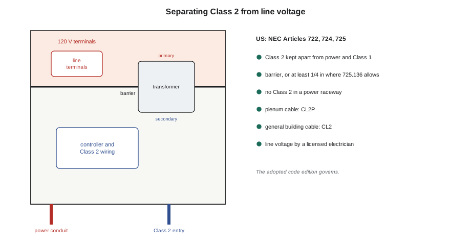
In practice this means separate cable entries, separate raceways and separate wire ducts for Class 2 and power wiring, and a barrier or separate compartment in any enclosure that holds both. It also means that a technician should never pull a Class 2 cable into an electrician's conduit carrying power conductors, however convenient the empty space looks, and never tie Class 2 cables to power conduits as their support where the code forbids it. On the roof, Tegan's conduit would enter the bottom left of the enclosure under the barrier, and Quillon's cables the bottom right, exactly as Callie had cut the gland plate in lesson 6.
Cable types and fire ratings
Class 2 circuits must be run in a cable type the code permits for the location. The most important property is how the cable behaves in a fire, because cables run through ceiling spaces and shafts where burning insulation can spread flame and smoke. Class 2 cables are marked CL2 for general use, CL2R for risers and CL2P for plenums, with Class 3 and communications cable types allowed as substitutes as the code lists. A plenum-rated cable can be used anywhere a lower rating could.
| Location | Class 2 cable type |
|---|---|
| General building use | CL2, or a higher type |
| Vertical shafts and risers | CL2R or CL2P |
| Plenums and air-handling spaces | CL2P |
| Outdoors or wet locations | A type rated for the conditions, or in a raceway |
Ninefield's office floors had ceiling return plenums, where the space above the ceiling tile is part of the air path back to the air handlers. Every Class 2 cable Quillon ran above those ceilings had to be plenum-rated: CL2P or higher. Declan's material list specified plenum-rated cable for the whole job so that no one would grab the wrong reel. The trunk would run in the existing communications riser from the penthouse to the second floor, then through the podium ceiling and out to the roof through a sleeved penetration.
Raceways, supports and protection
Class 2 cable is often run without conduit inside buildings, supported by the structure with hangers, J-hooks or cable trays, as the code and the specification allow. It should be supported at the intervals the specification sets, not laid on ceiling tiles or tied to sprinkler pipes, ducts or the hangers of other trades, and it should be kept away from hot surfaces and sources of interference such as drive output cables, as BAS-120 described at Ninefield. Where cable is exposed to damage, for example on a roof, in a mechanical room at low level or where it rises from a floor, it runs in conduit. Penetrations through fire separations must be firestopped with a listed system, as the insulator program's firestopping course describes; the controls contractor arranges this with the firestop trade or does it under a listed system if trained.
On a roof, cable must suit sunlight, water and temperature extremes. Most building cable is not rated for sunlight, so outdoor runs are in conduit, typically rigid metal or EMT with weatherproof fittings, or liquid-tight flexible conduit for the last short connection to the equipment. Conduit is supported on roof blocks or the unit's curb, not laid loose, and roof penetrations are made and sealed by the roofing contractor as part of the roof system.
Worked problem
Checking conduit fill
Five Class 2 cables will share a 3/4 in EMT conduit from the roof penetration to the panel: three of 0.20 in diameter, one of 0.28 in and one of 0.24 in. The conduit's internal area is about 0.533 in². The project specification limits fill to 40 in 100. Is it within the limit?
Show solution
- Area of a cable: π × d² ÷ 4.
- 0.20 in cables: 3 × 0.0314 = 0.0942 in².
- 0.28 in cable: 0.0616 in².
- 0.24 in cable: 0.0452 in².
- Total: 0.0942 + 0.0616 + 0.0452 = 0.201 in².
- Fill: 0.201 ÷ 0.533 = 0.377, about 38 in 100.
Answer: Within the 40 in 100 limit, with little room to spare. Declan upsized the roof conduit one trade size so that the December work on RTU-2 to RTU-4 could share the route.
Interference and signal quality
The code is about safety; signal quality is about getting the right readings. Low-level signals pick up interference from nearby power wiring, motors and especially variable frequency drive output cables. The habits from BAS-120 apply to every run: shielded twisted pair for analog signals and networks where the maker specifies it, shields grounded at one end only, runs kept apart from drive and motor cables and crossing them at right angles where they must cross, and no low-level signal sharing a cable with switched 24 volt loads where avoidable. On the Ninefield roof, the trunk route kept well away from the condenser fan motor leads inside the unit.
Length limits
Each kind of Class 2 circuit has a practical length limit set by the signal, not the code. Power runs are limited by voltage drop, as lesson 3 calculated. Thermistor inputs tolerate long runs because the wire resistance is small compared with the sensor's. Voltage signals are vulnerable to drop and noise on long runs, which is why 4 to 20 milliamp signals are preferred for long distances. Network trunks have their own limits, set by the protocol and baud rate, as lesson 10 explains: an RS-485 trunk for BACnet MS/TP is commonly limited to about 4,000 ft per segment on suitable cable. Declan measured the trunk route on the drawings at about 460 ft, well within it.
Worked problem
Voltage drop on a long power run
A remote sensor transmitter on the roof draws 2 VA from a 24 V supply 280 ft away on 18 AWG copper (6.4 ohms per 1,000 ft). What is the voltage drop?
Show solution
- Current: 2 ÷ 24 = 0.083 A.
- Round trip: 560 ft; resistance 560 × 6.4 ÷ 1,000 = 3.58 ohms.
- Drop: 0.083 × 3.58 = 0.30 V.
Answer: About 0.3 volts, which is acceptable. The same run feeding a 10 VA actuator would drop about 1.5 volts, which is why the panel and its transformer were put next to the unit.
What Callie took away
Walking back to the stairs, Callie listed what the survey had settled. The panel would mount on the curb on the north side, in shade, with its sun shield on the south face. Kelso Electric would bring the 120 volt feed and disconnect. Quillon's cables would be plenum-rated, run in the riser and podium ceiling on their own supports, and enter the roof through a sleeved, sealed penetration into conduit to the panel. The trunk would be about 460 ft long. Nothing would share a raceway with Tegan's wiring. "Most code problems are scope problems," Declan said. "If everyone knows exactly what's theirs, the wiring follows the rules almost by itself."
Inspection and records
Electrical work is inspected, and controls work is affected by that inspection even where the controls contractor's own wiring does not need a permit. The inspector looks at the electrician's feed, the disconnect, the grounding of the panel and its certification label, and often at the separation between Class 2 and line-voltage wiring inside the panel. A panel with no certification label, a Class 2 cable sharing the electrician's conduit, or an enclosure entry that does not keep its rating can hold up the whole job. On a Columbus job, the electrician's permit covers the line-voltage work, and the city inspector may ask to see the panel's listing.
Quillon kept a short record in each job file of what was inspected, by whom and when, alongside the electrician's notification or permit number. For RTU-1, Declan added a line to the work order asking Tegan to tell Quillon when the inspection was booked, so that Callie could be on the roof to open the panel and answer questions about the Class 2 side. Inspectors are far easier to satisfy when the person who did the work is there with the drawings, and an inspection that passes the first time is cheaper for everyone.
Common mistakes
MistakeCalling a circuit Class 2 because it uses thin wire.
InsteadA circuit is Class 2 because of its listed power-limited source and what is connected to it.
MistakePulling Class 2 cable into an electrician's conduit with power conductors.
InsteadKeep Class 2 and power in separate raceways and compartments except as the code permits.
MistakeUsing general-purpose cable in a plenum.
InsteadUse plenum-rated cable, CL2P, in air-handling spaces.
MistakeLeaving cable exposed to sunlight and damage on a roof.
InsteadRun outdoor cable in suitable conduit with weatherproof fittings.
MistakeAssuming the controls contractor wires the transformer primary.
InsteadLine-voltage work is electricians' work; write both scopes down.
Summary and key terms
- The United States uses the National Electrical Code as adopted by states and cities, including Ohio and Columbus.
- Class 2 circuits are power-limited by a listed source and can be installed with lighter methods.
- In the 2023 NEC, Class 2 is in Article 725, Class 1 in Article 724 and the cables in Article 722.
- Class 2 wiring must be kept separate from power and Class 1 wiring except with barriers or spacings the code allows.
- Cable must suit its location: CL2 in general, CL2P in plenums, rated types or conduit outdoors.
- Line-voltage feeds are electricians' work; licensing and permit rules for low-voltage work vary and must be confirmed.
- Practical length limits come from voltage drop, noise and protocol limits.
- Class 2 circuit
- A circuit supplied by a listed power-limited source, installed with lighter wiring methods.
- Class 1 circuit
- A remote-control or signaling circuit installed with methods close to power wiring.
- Plenum
- A space that forms part of the air distribution system, such as a ceiling return.
- CL2P
- The cable type for Class 2 circuits in plenums.
- Raceway
- An enclosed channel, such as conduit, for holding wires and cables.
- Conduit fill
- The fraction of a conduit's internal area occupied by its conductors or cables.
- Barrier
- A permanent partition separating circuits of different classes.
Practice problems
Work each problem on paper first, then reveal the answer to check.
What makes a circuit Class 2?
Show answer
Its listed power-limited source and the fact that nothing on it is fed from a higher-class source.
Which cable rating is needed in a ceiling return plenum?
Show answer
CL2P or higher.
Where are Class 1 circuits found in the 2023 NEC?
Show answer
Article 724.
Four cables of 0.24 in share a conduit with 0.533 in² internal area. What is the fill?
Show answer
4 × 0.0452 = 0.181 in²; 0.181 ÷ 0.533 = 0.34, 34 in 100.
Who installs the 120 volt feed to a controls panel?
Show answer
A licensed electrician, under the electrical contractor's notification or permit.
Lesson quiz · 5 questions
Score 60% or more to complete this lesson.
Create a free account to save your progress, take quizzes and earn a certificate.