
BAS-210 · Lesson 5 of 12 · 21 min
Wiring practice and panel layout
▶ Video coming soon A video version of this lesson is on the way.
On Wednesday, October 21, Callie spent the day in the panel shop building the RTU-1 control panel with Prakash. The controller was configured and tested, the program was nearly ready, and the enclosure, back panel, rails, wire duct and terminals had arrived the week before. Declan's drawing showed what went in the panel; it did not show where each part should sit or how the wires should run. "The drawing tells you what," Prakash said. "Good practice tells you how. The next technician to open this door will know in ten seconds whether we cared." This lesson covers how a control panel is laid out and wired, using the RTU-1 panel as the example. Lesson 6 covers the enclosure, terminals and labels.
Why layout matters
A control panel is a small building of its own. It has to fit the parts with room for heat to escape, keep line-voltage and low-voltage circuits apart, bring field wires in neatly, and let a technician years from now test, replace and add parts without unwiring everything else. A panel laid out well is quicker to build, easier to check out and far easier to service. A panel laid out badly hides faults, invites mistakes and often has to be rebuilt the first time something is added. Good layout is mostly a matter of a few consistent habits.
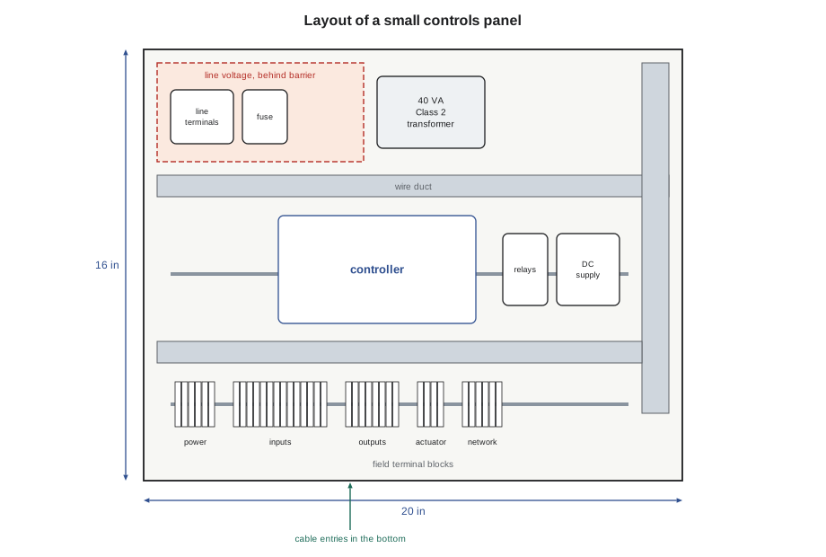
The layout principles
Most controls panels follow the same pattern. Line-voltage parts, where there are any, go in one corner, usually the top, behind a barrier or in a separate compartment, so that a technician working on the low-voltage side cannot touch them by accident. The transformer and its fuses sit next to that section, because the transformer is where line voltage becomes Class 2 power. The controller and its expansion modules go in the middle, at a comfortable height for reading lights and connecting a laptop. Interposing relays and power supplies go beside or below the controller. Field terminal blocks go along the bottom or one side, nearest the cable entries, so that field wires land on terminals rather than traveling across the panel. Wire ducts run between the rows.
Space matters as much as position. Controllers and power supplies give off heat and need clearance above and below for air to move, as their installation guides state. Parts need room around them for hands and tools. And every panel should leave space for growth: a spare section of rail and room in the ducts, so that one more relay or expansion module can be added without rebuilding. Declan's rule of thumb at Quillon was that a new panel should be no more than about three quarters full on the day it ships.
| Zone | What goes there | Why |
|---|---|---|
| Top, behind a barrier | Line-voltage terminals, fuses, disconnect if any | Keeps line voltage away from low-voltage work |
| Beside the line-voltage section | Class 2 transformer and secondary fuse | Short, direct path from line to low voltage |
| Middle | Controller and expansion modules | Easy to see lights and connect a laptop |
| Beside the controller | Interposing relays, DC supplies, network devices | Short wiring to the outputs they serve |
| Bottom, near cable entries | Field terminal blocks | Field wires land without crossing the panel |
| Between rows | Slotted wire duct | Neat routing and room for changes |
DIN rail and terminal blocks
Almost everything in a modern controls panel mounts on 35 millimeter DIN rail screwed to the back panel. Controllers, relays, power supplies, fuse holders and terminal blocks clip on and slide along it, so parts can be added or moved without drilling. Terminal blocks are the junction between the panel's internal wiring and the field wiring. Each block is a small insulated housing with a screw or spring clamp at each end and a metal bridge between them. Blocks come in widths of about 5 to 8 millimeters, with end plates, end stops that hold the row in place and jumper bars that link adjacent blocks for distributing 24 volts or common.
Worked problem
Sizing a terminal rail
The RTU-1 panel needs 40 field and power distribution terminals, plus 20 in 100 spare. Each terminal block is 0.205 in wide, and each end stop is 0.37 in. There are two groups, each needing two end stops. How long must the terminal rail be?
Show solution
- Spares: 40 × 0.2 = 8, so 48 terminals.
- Terminals: 48 × 0.205 = 9.84 in.
- End stops: 4 × 0.37 = 1.48 in.
- Total: 9.84 + 1.48 = 11.32 in.
Answer: About 11.3 in, so a 12 in rail with a little room left.
Wire duct
Slotted wire duct, often called by one maker's brand name, is a plastic channel with fingers along the sides and a snap-on cover. Wires run inside the duct and leave through the slots at the point closest to their terminal. Duct keeps the panel neat, protects the wires and makes it easy to trace and add wires. A duct packed full is almost as bad as no duct, because adding a wire means pulling the cover off a solid mass. A common rule is to fill a duct no more than about half when the panel is built. Line-voltage and Class 2 wiring must run in separate ducts or be separated as the electrical code requires, as lesson 7 explains.
Choosing and preparing wire
Panel wiring is usually stranded copper, because stranded wire is flexible and survives the door being opened and closed. The size follows the load and the design: commonly 18 AWG for 24 volt power and actuator circuits and 22 to 18 AWG for signals, with the insulation rated for the panel's highest voltage where circuits are near each other. Many contractors use a color standard so that a technician can tell circuits apart at a glance. Quillon's company standard used red for 24 volt hot, blue for 24 volt common and white for signals, with line-voltage colors left to the electrical code and the electrician.
Stranded wire landed in a screw terminal should be fitted with a ferrule, a small metal sleeve crimped over the stripped end. The ferrule keeps the strands together, prevents stray strands from bridging to the next terminal and gives the screw a solid surface to clamp. Strip length matters: too short and the clamp grips insulation; too long and bare copper shows past the terminal. Each terminal should normally hold one wire, unless the terminal is rated for two or a twin ferrule is used. Screws should be tightened to the torque the terminal maker gives, not by feel alone, because both loose and crushed connections fail.
| Practice | Why |
|---|---|
| Use ferrules on stranded wire in screw terminals | No stray strands; solid clamping |
| One wire per terminal unless rated for two | Both wires held securely |
| Strip to the length the terminal needs | No clamped insulation, no exposed copper |
| Tighten to the stated torque | Avoids loose or crushed connections |
| Tug-test each wire after landing it | Catches a wire that is not clamped |
| Leave a small service loop at devices | Allows a re-termination without a new wire |
| Mark both ends of every wire | Lets anyone trace a circuit |
Wire numbering
Every wire in a well-built panel is marked at both ends with a number or name that matches the wiring diagram. Markers may be printed sleeves, wrap-around labels or clip-on markers. The numbering scheme varies between contractors, but it should let anyone find a wire on the drawing from the marker, and the marker from the drawing. A common approach is to name each wire after the terminal it lands on at the controller, such as UI3 or RO2. Quillon's standard was to mark each wire with its controller terminal and its field terminal number, separated by a slash.
Callie found that marking took almost as long as wiring. Prakash insisted anyway. "Two years from now, at seven in the morning, with the shops complaining and the unit not starting, somebody is going to open this panel," he said. "Every marker you print now saves them ten minutes then. Sometimes that somebody will be you."
Routing and dressing
Wires should run from the terminal into the nearest duct slot, along the duct and out of the slot nearest their other end, with no wires crossing the face of the panel outside the duct. Wires should not be stretched tight, and should not be bundled so tightly that heat cannot escape. Where wires cross from the back panel to devices on the door, such as a switch or indicator, they run as a flexible bundle with a loop, protected from chafing at the hinge. Inside the duct, signal wires are kept away from wires carrying switched loads where possible, to reduce interference, and line-voltage and Class 2 wiring are kept apart as the code requires.
Field terminals and the controller
Some contractors land field wires directly on the controller's pluggable terminals, which saves terminal blocks and keeps the panel small. Others land all field wires on a terminal strip and wire the controller from the strip, which keeps the controller's terminals untouched when field wiring changes and makes testing easier, because each point can be disconnected at the strip. Quillon's practice for plant controllers was the terminal strip, with knife-disconnect blocks on inputs so that a technician could isolate a sensor and inject a test signal without removing any wires. For small terminal unit controllers, field wires went straight to the controller.
For RTU-1, the field terminal strip had five groups in the order they would be met in the field: power distribution, inputs, relay outputs to the unit, the economizer actuator and the network trunk. Each group was separated by an end plate and a group marker. The network terminals included a landing point for the cable shield, connected at this panel only, as lesson 10 explains.
Building the RTU-1 panel
By mid-morning the back panel was laid out on the bench. Callie measured and cut the DIN rails and wire duct, deburred the cut ends, mounted them with the screws in the parts kit and clipped on the parts in the order on Declan's drawing. Prakash checked the clearances above and below the controller against its installation guide before anything was wired. Then they wired the panel, transformer first, then the controller power, then each group of points in turn, marking each wire and tug-testing each connection. Callie kept a highlighter and a copy of the wiring diagram on the bench and highlighted each wire on the drawing as she finished it, so that nothing was missed and nothing was wired twice.
At the end, Prakash did what he called the flashlight test: he shone a light into the panel and looked for any bare copper, any strand outside a terminal, any wire crossing outside a duct and any unmarked wire. He found two missing markers and one ferrule crimped crooked. Callie fixed them. Then the panel went on the shelf for Sophie to load and test the program, and for lesson 6's enclosure work in the afternoon.
Testing the panel before it leaves
Before a panel goes to site, it is powered on the bench and tested. Quillon's shop had a test supply, a bank of indicator lamps and a set of resistors and signal sources that could be clipped to the field terminals. With the program loaded, each input was given a known signal at its field terminal, not at the controller, so that the panel's internal wiring was proved along with the configuration. Each output was commanded and its lamp, meter reading or relay contact checked at the field terminal. Faults found on the bench take minutes to fix with the panel lying flat under good light. The same faults found on a roof in December take an hour and a cold pair of hands.
Callie found one fault this way on the RTU-1 panel: the jumper bar distributing 24 volt common had been cut one terminal short, so the economizer actuator's common terminal was not connected. The actuator would have done nothing on site, and the meter would have shown a correct 2 to 10 volt signal at the controller, which would have sent a technician looking at the actuator. On the bench, the lamp test found it in seconds.
| Bench test | Proves |
|---|---|
| Signal injected at each field input terminal | Internal wiring and input configuration together |
| Each output commanded and checked at its field terminal | Output wiring, relays and output configuration |
| Power distribution checked at every powered terminal | Jumper bars, fuses and the transformer |
| Network port connected to a test trunk | Address, baud rate and communication |
Common mistakes
MistakeMounting parts first and planning the wiring later.
InsteadLay out the zones, rails and ducts first, with heat clearances and room for growth.
MistakeLanding stranded wire without ferrules.
InsteadFit ferrules so that no strands escape and the clamp grips solidly.
MistakePacking wire duct full.
InsteadFill duct no more than about half so that changes are possible.
MistakeLeaving wires unmarked.
InsteadMark both ends of every wire to match the diagram.
MistakeRunning line-voltage and Class 2 wires in the same duct.
InsteadKeep them in separate ducts or separated as the code requires.
Summary and key terms
- A panel layout separates line voltage, places the transformer nearby, puts the controller in the middle and the field terminals near the cable entries.
- Leave heat clearances, working room and spare space for growth; a new panel should not ship full.
- Parts mount on 35 millimeter DIN rail; terminal blocks join internal and field wiring.
- Slotted wire duct keeps wiring neat; fill it no more than about half.
- Use stranded wire with ferrules, one wire per terminal, correct strip length and torque, and a color standard.
- Mark both ends of every wire to match the wiring diagram.
- Field terminal strips with disconnect blocks make testing and changes easier.
- DIN rail
- A standard 35 millimeter steel rail on which panel parts clip and slide.
- Terminal block
- An insulated housing with clamps that joins two or more wires.
- End stop
- A clamp that holds a row of terminal blocks in place on the rail.
- Jumper bar
- A link that connects adjacent terminal blocks, used to distribute power or common.
- Wire duct
- A slotted plastic channel with a cover that carries panel wiring.
- Ferrule
- A metal sleeve crimped over stranded wire before it is landed in a terminal.
- Wire marker
- A label at each end of a wire matching the wiring diagram.
- Disconnect terminal
- A terminal block with a knife or switch that isolates a circuit for testing.
- Service loop
- A little extra wire left at a device for re-termination.
Practice problems
Work each problem on paper first, then reveal the answer to check.
Where should field terminal blocks usually go in a panel?
Show answer
Along the bottom or one side, nearest the cable entries.
A rail must hold 30 terminals at 0.244 in and 4 end stops at 0.37 in. How long?
Show answer
30 × 0.244 + 4 × 0.37 = 7.32 + 1.48 = 8.8 in.
Why fit ferrules to stranded wire?
Show answer
To keep strands together, prevent bridging and give the clamp a solid surface.
How full should wire duct be when a panel is built?
Show answer
No more than about half.
What is the flashlight test?
Show answer
Looking into the finished panel for bare copper, stray strands, wires outside ducts and missing markers.
Lesson quiz · 5 questions
Score 60% or more to complete this lesson.
Create a free account to save your progress, take quizzes and earn a certificate.