
BAS-210 · Lesson 1 of 12 · 23 min
The DDC controller and its parts
▶ Video coming soon A video version of this lesson is on the way.
On Monday, September 14, at the start of her second week at Quillon Building Controls, Callie Rintoul spent the morning in the panel shop at the back of the Westerville Road office. Prakash Deshmukh had put a spare plant controller on the bench, still in its box, beside an old one that Quillon had taken out of a Harcastle College building in 2023. "Before you wire one of these, you should know what's inside it," he said. "When something goes wrong in the field, half the battle is knowing which part of the controller to suspect." He opened both, laid out the manuals, and asked Callie to find each part on the circuit boards as he named it.
This course is about the controller: the box at the center of every building automation system. BAS-120 covered the field devices at the ends of the wires, and BAS-130 covered the control logic that decides what to do. This course covers the hardware in between: what a direct digital controller is made of, the kinds of controllers found in buildings, how they are powered and grounded, how their inputs and outputs are wired, how they are built into panels and connected into networks, and how a technician configures, backs up and checks one out. The last lesson follows the replacement of a rooftop unit controller at Ninefield Tower from start to finish.
What direct digital control means
A direct digital controller, usually called a DDC controller, is a small computer built to read sensors, run control programs and drive actuators. The word direct means that the controller itself reads the sensor and drives the output, with no separate analog controller in between. The word digital means that the decisions are made by a microprocessor working with numbers. Before DDC, building loops were run by pneumatic receiver-controllers or by analog electronic controllers, as BAS-130 described. A DDC controller does the same job by converting each sensor signal to a number, running the control program on those numbers many times a second, and converting the results back into signals that move valves, dampers and fans.
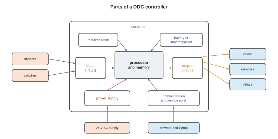
Every DDC controller, from a small box on a variable air volume terminal to a large plant controller, does the same four things in a repeating cycle. It reads its inputs. It runs its program, which includes the control loops, schedules, alarms and logic. It writes its outputs. And it communicates with the rest of the system. The time taken to complete one cycle is called the scan time, and in building controllers it is usually a fraction of a second to a second or two. Because building processes are slow compared with this, a controller appears to act continuously, even though it is really taking snapshots.
The processor and memory
At the heart of the controller is a microprocessor, the chip that runs the program. Around it are several kinds of memory, and knowing which is which explains much of what happens when a controller loses power. The firmware is the controller's own operating software, written by the manufacturer and stored in non-volatile flash memory. It knows how to read an input, run a PID block and talk on the network. The application program and database are the parts the controls contractor writes: the control sequence, the point configuration, the setpoints and schedules for this particular piece of equipment. Depending on the product, these are stored in flash memory too, or in battery-backed memory, or in a combination.
Working memory, called RAM, holds the values the controller is using right now: the latest sensor readings, the state of timers, the integral term of each loop and the values of points written from the front end. On most modern controllers this memory is lost when power is removed, and the controller rebuilds it from the stored program when it restarts. On some, important values are saved to flash at intervals or when they change, so that a setpoint changed by an operator survives a power failure. Prakash's warning was simple: "Never assume a value you typed into a controller will be there tomorrow. Find out how that product stores it, and make sure it's in the backup." Lesson 9 returns to this.
| Memory | What it holds | Survives a power failure? |
|---|---|---|
| Firmware (flash) | The manufacturer's operating software | Yes |
| Application and database | The program, point setup, schedules and setpoints for this job | Yes on most current products; on some older ones only with a good battery |
| Working memory (RAM) | Live values: readings, timers, loop states, values written by operators | Usually no; rebuilt at restart unless the product saves them |
| Trend and alarm buffers | Recent history stored in the controller | Depends on the product; often lost on older controllers |
The real-time clock and backup power
A controller needs to know the time and date to run schedules, time-stamp alarms and trends, and switch between daylight saving and standard time. The real-time clock is a small circuit that keeps time even when the controller is off, powered by a coin battery or a supercapacitor. A supercapacitor holds enough energy to keep the clock running for days rather than years, which is fine in a building where power is rarely off for long but can catch out a controller that sits on a shelf. In networked systems, the supervisory controller or front end usually synchronizes every controller's clock at intervals, so a drifting clock in one controller is corrected automatically, as long as the network is working.
The old controller on the bench had a coin battery soldered to the board, with a date written on it in marker: 2011. Prakash explained that controllers of that era used the battery to protect the application program as well as the clock, and that a flat battery followed by a power cut could wipe the program completely. Some buildings still have controllers like that. A dead battery alarm, or a controller that shows the wrong date after a power failure, is a warning that should be acted on before the next outage, not after it.
Inputs
Inputs are the circuits that read the outside world. Each input terminal pair connects to a sensor or a switch. The input circuit conditions the signal, converts it from an analog voltage, current or resistance into a number with an analog-to-digital converter, and hands that number to the program. The resolution of the converter, often 12 to 16 bits on current controllers, sets how finely the input can tell one value from the next. A 12-bit converter divides its range into 4,096 steps; on a 0 to 10 volt input that is about 2.4 millivolts per step, far finer than any building sensor needs.
Worked problem
Input resolution
A controller's analog input converts 0 to 10 volts with a 12-bit converter. The input reads a 0 to 10 volt duct static pressure transmitter with a range of 0 to 2 in. w.c.. What is the smallest change in pressure the input can resolve?
Show solution
- Steps: 2 to the power 12 = 4,096.
- Pressure per step: 2 ÷ 4,096 = 0.000488 in. w.c.
Answer: About 0.0005 in. w.c. The transmitter's own accuracy, typically about 0.01 in. w.c., limits the reading long before the input does.
Inputs come in two broad kinds. Analog inputs read a value that can vary continuously: a thermistor's resistance, a transmitter's 0 to 10 volt or 4 to 20 milliamp signal. Binary inputs, also called digital inputs, read whether a contact is open or closed: a fan status switch, a filter switch, an alarm contact from a chiller. Many current controllers have universal inputs, which can be configured in software to be any of these. Lesson 4 covers input types and how to set them up.
Outputs
Outputs are the circuits that act on the outside world. Analog outputs produce a variable signal, usually 0 to 10 volts or 2 to 10 volts, to drive a modulating valve or damper actuator or to set a drive's speed. Binary outputs switch something on or off, either with a small relay whose contacts close a separate circuit, or with a solid-state switch called a triac that switches 24 volts AC directly. Some controllers have floating outputs, pairs of binary outputs that drive an actuator open or closed, as BAS-130 explained. Many have universal outputs that can be set up as analog or binary. Each kind of output has limits on the voltage and current it can handle, and exceeding those limits is one of the commonest ways to damage a controller.
Prakash turned the old controller over and showed Callie a small black component next to one of the output terminals, scorched brown. "Somebody wired a contactor coil straight to that triac in 2019," he said. "It worked for four years, then it didn't." The contactor coil drew far more current when it first pulled in than the triac was rated for. Lesson 4 shows how to read output ratings and when an interposing relay is needed.
The power supply
Almost all building controllers in North America run on 24 volts AC from a Class 2 transformer, and many also accept 24 volts DC. Inside the controller, a power supply circuit rectifies and regulates this into the low DC voltages the electronics use, typically 5 volts and 3.3 volts, and often a 24 volt DC or 15 volt DC supply that the controller offers on terminals for powering transmitters. A controller's power consumption is listed in volt-amperes in its data sheet, and the transformer must be sized for the controller plus everything else it feeds. Lesson 3 covers power, transformers and grounding in detail, because many intermittent controller faults turn out to be power faults.
Communication ports
A controller in a building system rarely works alone. It shares information with other controllers, sends alarms and trends to a supervisory controller and accepts setpoints and commands from operators. For this it has one or more communication ports. On small controllers this is often an RS-485 port for a BACnet MS/TP or Modbus RTU trunk. On larger controllers it is an Ethernet port for BACnet/IP or another IP protocol, sometimes with an RS-485 port as well so that the controller can act as a router to small devices below it. Most controllers also have a service port, a USB port, a dedicated jack or a short-range wireless connection, so that a technician with a laptop or phone app can connect directly to that one controller. Lesson 10 covers networks; BAS-310 covers BACnet in depth.
Status lights and the front panel
Every controller has a few indicator lights, and they are the first thing an experienced technician looks at. Typical lights show that power is present, that the processor is running its program (often a slowly blinking heartbeat), that the network port is sending and receiving, and the state of each binary output. Some controllers have a small display and buttons for basic setup; others have nothing but lights and must be configured with software. Callie found the light descriptions in both manuals and noticed they were different: on one product a steady green light meant all was well, and on the other it meant the controller was stuck in its boot loader waiting for a program. "That's why you read the manual for the product in front of you," Prakash said. "Don't trust what the lights meant on the last one."
| Light | Usual meaning | If it is wrong |
|---|---|---|
| Power | Supply voltage present | Check the transformer, fuse and wiring |
| Run or heartbeat | Processor running the program | A steady or dark light can mean a crashed or missing program |
| Network transmit and receive | Traffic on the trunk or Ethernet | No receive light suggests wiring, termination or addressing faults |
| Output lights | Binary output commanded on | A light on with no action at the device points to wiring or the device |
Terminals and the physical package
The parts Callie would handle most were the terminals. On current controllers these are usually pluggable terminal blocks: the field wires are screwed or clamped into a removable plug, and the plug fits onto a header on the board. A controller can then be replaced without disconnecting every wire: unplug the blocks, swap the controller, plug them back in. Older controllers had fixed screw terminals soldered to the board. Terminals are labeled on the case, and the wiring diagrams in the manual show which terminals are inputs, outputs, power and communication. The controller mounts on DIN rail, a standard 35 millimeter steel rail, or with screws to a back panel inside an enclosure, as lessons 5 and 6 describe.
Controllers are built for the conditions inside a control panel or a mechanical room, not for weather. Data sheets give an operating temperature range, often around 32 to 122 °F for controllers, a humidity range without condensation, and a rating that says whether the controller needs to be inside an enclosure. A controller mounted on a rooftop unit, as in lesson 12, goes inside a weather-rated enclosure, and the designer checks that the enclosure will not overheat in summer sun or freeze in winter.
Opening the old controller
By the end of the morning Callie had a list. The 2011 controller had eight inputs, six relay outputs, four analog outputs, an RS-485 port and a 9-pin serial service port that needed an adapter cable nobody at Quillon could find. Its program lived in battery-backed memory. The new controller had twelve universal inputs, eight universal outputs, an Ethernet port, an RS-485 port, a USB service port and flash memory for the program, and its clock was backed by a supercapacitor rated to run for about a week without power. "Same four jobs," Prakash said. "Read, think, write, talk. It's just faster, and it forgets less."
He then set Callie a habit that would carry through the course: before working on any controller, write down its model, firmware version, network address and where its backup is kept. Those four facts would have saved Quillon two days on a Harcastle job the year before, when a controller had been replaced by one with different firmware and the old program would not load. Lesson 9 tells that story.
Common mistakes
MistakeAssuming every value in a controller survives a power failure.
InsteadCheck how the product stores setpoints and operator changes, and keep a current backup.
MistakeTrusting status lights from memory.
InsteadRead the manual for the product in front of you; the same color can mean different things on different controllers.
MistakeWiring a load straight to an output because the voltage matches.
InsteadCheck the output's current rating, including inrush, and use an interposing relay where needed.
MistakeIgnoring a clock or battery alarm.
InsteadA failing clock or battery can cost the schedule or even the program at the next power cut.
MistakeMounting a controller where it will overheat or get wet.
InsteadCheck the data sheet's temperature and humidity ranges and use a suitable enclosure.
Summary and key terms
- A DDC controller is a small computer that reads inputs, runs a program, writes outputs and communicates, in a repeating scan.
- Firmware is the manufacturer's software; the application program and database are written for the job; working memory holds live values.
- The real-time clock keeps time for schedules and time stamps, backed by a battery or supercapacitor.
- Inputs convert sensor signals to numbers; outputs convert numbers back to signals or switched circuits.
- Most controllers run on 24 volts AC from a Class 2 transformer.
- Communication ports connect the controller to trunks, Ethernet and a technician's laptop.
- Status lights, terminals and data sheets tell the technician what the controller is doing and how it must be installed.
- Direct digital control
- Control in which a microprocessor-based controller reads sensors and drives outputs directly.
- Scan time
- The time a controller takes to read its inputs, run its program and write its outputs once.
- Firmware
- The manufacturer's operating software stored in the controller.
- Application program
- The control sequence and configuration written for a particular job.
- Real-time clock
- The circuit that keeps the time and date, backed by a battery or supercapacitor.
- Analog-to-digital converter
- The circuit that turns an input voltage or current into a number.
- Triac
- A solid-state switch used in some binary outputs to switch 24 volts AC.
- Pluggable terminal block
- A removable connector that holds the field wires and plugs onto the controller.
- Service port
- A direct connection for a technician's laptop or tool.
Practice problems
Work each problem on paper first, then reveal the answer to check.
Name the four jobs a DDC controller does in every scan.
Show answer
Read inputs, run the program, write outputs and communicate.
Where is a controller's firmware stored?
Show answer
In non-volatile flash memory; it survives a power failure.
What does a supercapacitor do in a controller?
Show answer
It keeps the real-time clock running for a limited time when power is off.
How many steps does a 12-bit converter divide its range into?
Show answer
4,096.
What four facts should you record before working on a controller?
Show answer
Its model, firmware version, network address and where its backup is kept.
Lesson quiz · 5 questions
Score 60% or more to complete this lesson.
Create a free account to save your progress, take quizzes and earn a certificate.