
AUTO-410 · Lesson 8 of 12 · 20 min
Inverters, converters and the 12 V DC-DC
Bev bought a used hybrid crossover in the spring to serve as Ridgeline's courtesy car, partly so the shop would have one to learn on. On a hot afternoon, Simone returns from a parts run in it with the master warning light on and a message to have the hybrid system checked. The engine had started running constantly, and the car felt sluggish. Kiran connects the scan tool: a code for inverter cooling system performance and an inverter temperature climbing past 158 °F while parked. "Good timing," Marty says. "Today you learn what the power electronics do, and why they need their own coolant."
This lesson explains the power electronics that sit between the battery and everything else: the traction inverter, which drives the motor; the boost converter some hybrids use; the DC-DC converter that replaces the alternator; and the onboard charger. It covers how they switch, how they are cooled, and how to check them.
The traction inverter
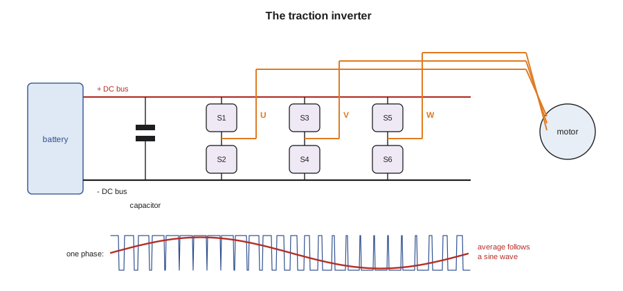
The battery supplies direct current at a steady voltage. The motor needs three-phase alternating current whose frequency, voltage and phase angle change continuously with speed and torque. The inverter makes that current. Inside are six electronic switches, two for each phase, arranged in three half-bridges between the positive and negative DC bus. By turning the switches on and off thousands of times a second in a precise pattern, the inverter connects each motor phase alternately to the positive and negative bus, so the average voltage on each phase follows a sine wave. This is pulse-width modulation, or PWM: the width of each pulse sets the average voltage, and the pattern of widths sets the shape and frequency of the wave.
The switches are power semiconductors. Most inverters use insulated-gate bipolar transistors, or IGBTs, made of silicon. Newer ones, especially in 800 volt vehicles, use silicon carbide MOSFETs, which switch faster and lose less energy, so the inverter runs cooler and the vehicle goes a little farther on the same charge. A large film capacitor across the DC bus smooths the current drawn from the battery, which is the capacitor the de-energizing lesson waited for. A control board reads the motor's current sensors and resolver and computes the switching pattern, and a gate driver board turns the switches on and off.
# Inverter: battery current for a given motor output, and the heat the power electronics must shed
v_bus = 360
for p_motor_kw, eff_motor, eff_inv in [(20, 0.94, 0.97), (60, 0.95, 0.975), (150, 0.93, 0.965)]:
    p_dc = p_motor_kw / (eff_motor * eff_inv)
    i_bus = p_dc * 1000 / v_bus
    inv_heat = p_dc * (1 - eff_inv)
print(f"motor {p_motor_kw:3} kW: battery supplies {p_dc:5.1f} kW at {i_bus:4.0f} A; inverter heat {inv_heat:4.1f} kW")motor 20 kW: battery supplies 21.9 kW at 61 A; inverter heat 0.7 kW motor 60 kW: battery supplies 64.8 kW at 180 A; inverter heat 1.6 kW motor 150 kW: battery supplies 167.1 kW at 464 A; inverter heat 5.8 kW
At full power, the inverter alone must shed several kilowatts of heat, from a module the size of a shoebox. That is why it sits on a liquid-cooled plate, and why the courtesy car's warning matters.
Why higher voltage helps
Power is voltage times current, so doubling the battery's voltage halves the current for the same power. Lower current means thinner, lighter cables, smaller losses in the wiring and the switches, and faster DC charging without overheating the charge cable. That is why many newer electric vehicles use an 800 volt architecture instead of 400 volts. For technicians, an 800 volt system is no different in principle, but the shock hazard is greater and the PPE and meter must be rated for it: class 0 gloves cover up to 1,500 volts DC and a CAT III 1,000 volt meter covers an 800 volt bus with margin.
The boost converter in hybrids
Some hybrids, including many power-split designs, use a modest battery voltage, around 200 volts in Ines's car, but run their motors at a much higher voltage, up to about 650 volts, to make more power without larger currents. A boost converter between the battery and the inverter raises the voltage. It uses an inductor and switches: the switch stores energy in the inductor's magnetic field, then releases it into the bus at a higher voltage. When the motor regenerates, the converter works in reverse to bring the voltage back down to the battery's level. A technician reading scan data on such a car sees two voltages: the battery voltage and the higher system voltage after the boost converter.
The DC-DC converter
An electrified vehicle has no alternator, so the DC-DC converter charges the 12 volt battery and runs the vehicle's ordinary electrical loads whenever the high-voltage system is ready. It steps the traction voltage down to about 13.5 to 14.8 volts, delivering perhaps 1.5 to 3 kilowatts, and it is usually cooled by the same loop as the inverter. In Dr. Singh's spring visit, her weak 12 volt battery had been blamed on the converter until Kiran tested both: the converter held a steady 14.3 volts with every load switched on, and the battery failed its load test. A converter that has failed, or that has limited its output because it is hot, shows as a 12 volt system voltage that falls toward the battery's own voltage, about 12.5 volts, with the vehicle ready.
# DC-DC converter check: can it carry the 12 V loads with margin?
rating_w = 2500
setpoint_v = 14.3
loads_w = {"modules and lighting": 420, "blower on high": 380, "heated seats x2": 180, "rear defrost": 220,
           "wipers and headlights": 210, "battery charging": 300, "coolant pumps": 160}
total = sum(loads_w.values())
amps = total / setpoint_v
print(f"total 12 V load {total} W, {amps:.0f} A at {setpoint_v} V; {total / rating_w:.0%} of the converter's rating")
measured_v_ready = 14.2
verdict = "converter supplying the bus" if measured_v_ready > 13.2 else "converter not supplying: check its enable, fuse, output cable and temperature"
print(f"measured with vehicle ready and these loads on: {measured_v_ready} V -> {verdict}")total 12 V load 1870 W, 131 A at 14.3 V; 75% of the converter's rating measured with vehicle ready and these loads on: 14.2 V -> converter supplying the bus
The onboard charger
A plug-in vehicle's onboard charger converts alternating current from a home or public Level 2 station into direct current at the battery's voltage. Its rating, typically 7 to 11 kilowatts, and sometimes more, limits how fast the vehicle charges from AC, whatever the station can supply. During DC fast charging, the onboard charger is bypassed: the station's own large converter supplies DC straight to the battery through contactors in the charge path. A growing number of onboard chargers are bidirectional, able to supply AC from the battery to a power tool, a house during an outage or the grid, called vehicle-to-load, vehicle-to-home and vehicle-to-grid. The charging lesson covers the whole charging system.
| Component | Converts | Typical rating | Cooled by |
|---|---|---|---|
| Traction inverter | Battery DC to three-phase motor AC, and back | 100 to 300 kW | Liquid |
| Boost converter (some hybrids) | Battery DC to a higher DC system voltage | 20 to 60 kW | Liquid |
| DC-DC converter | High-voltage DC to 12 to 14.8 V DC | 1.5 to 3 kW | Liquid or air |
| Onboard charger | Grid AC to battery DC | 7 to 11 kW, some higher | Liquid |
Cooling the power electronics
Power semiconductors fail quickly if they overheat, so most electrified vehicles give the inverter, converters and charger their own coolant loop, separate from the engine's, run at a lower temperature by an electric pump and a small radiator. Many hybrids have this second loop with its own reservoir; electric vehicles may share one loop between the power electronics, the motor and the battery through valves. The loop is filled with the maker's coolant and bled with the scan tool, which runs the electric pump while the technician tops up.
The courtesy car's data point straight at that loop. The inverter temperature climbs steadily whether the car is moving or parked, and the electric pump's commanded speed is high while its feedback signal reports zero. With the hood open and the vehicle ready, Kiran feels the pump: it is cold and silent. The coolant level is correct. She checks the pump's 12 volt circuit as the electrical course taught her: battery voltage and a good ground arrive at its connector when commanded, but the pump does not turn. A failed inverter coolant pump is a known fault on this model, listed in a bulletin. No high-voltage component needs to be opened; the pump runs on 12 volts. She replaces it, refills the loop with the specified coolant, runs the scan tool's bleeding routine and clears the code.
# Inverter coolant loop: temperature rise from the electronics' heat at the coolant flow rate
cp = 3.6                  # kJ per kg per degree, glycol coolant
for label, flow_lpm in [("pump failed (thermosiphon only)", 0.4), ("new pump", 10.0)]:
    heat_kw = 2.2         # inverter, boost converter and DC-DC at moderate driving
    mass_kg_s = flow_lpm / 60 * 1.05
    rise = heat_kw / (mass_kg_s * cp)
print(f"{label:32}: coolant rises {rise * 1.8:5.1f} F through the electronics")pump failed (thermosiphon only) : coolant rises 157.1 F through the electronics new pump : coolant rises 6.3 F through the electronics
With almost no flow, the coolant cannot carry the heat away, and the inverter protects itself by limiting power, which is why the engine ran constantly and the car felt sluggish. After the repair, a test drive on a hot afternoon holds the inverter temperature about 36 °F above the outside air, as the specification expects.
Checking power electronics
Most inverter and converter faults are found with the scan tool, not a meter. The modules report their temperatures, voltages and currents, their switch and sensor faults, and the commanded and actual values for their pumps. A technician compares the readings with the specification and with each other: the inverter's input voltage should match the battery's, its three phase currents should be balanced, and its temperature should follow load. Internal faults in an inverter or converter are repaired by replacing the unit, because the semiconductors and boards inside are not serviceable, and a replacement unit usually needs a scan tool procedure such as a resolver offset learn or a programming step.
Where measurements on high-voltage circuits are needed, they are made with the system de-energized whenever possible, such as resistance checks of motor windings and insulation tests. Live measurements on high-voltage circuits are made only when the maker's procedure calls for them, by qualified people with full protection and approved probes.
Worked problem
Sizing a DC-DC converter load
A vehicle's 12 volt loads total 1,850 watts on a cold night with every heater on. Its DC-DC converter is rated 2.2 kilowatts at 14.0 volts. What current does it supply, and how much margin is left?
Show solution
- Current: 1,850 ÷ 14.0 = 132 amperes.
- Margin: 2,200 − 1,850 = 350 watts, about 16 percent of the rating.
Answer: About 132 amperes with about 16 percent margin; a hot converter that derates could fall short.
Reading the inverter's data
The courtesy car's repair gave Kiran a chance to read a healthy inverter's data for comparison, so she saved a recording to the shop's reference folder. On a steady drive, the three phase currents reported by the inverter are equal in size and spaced evenly in time; the DC input voltage matches the battery's voltage within a few volts; the inverter temperature rises with load and falls when coasting; and the boost converter's output, on this hybrid, rises from the battery's voltage toward its maximum when the driver asks for full power. A phase current that reads consistently lower than the others, an input voltage far below the battery's, or a temperature that keeps climbing at light load would each point at a different fault.
She also notes what the data cannot show. The scan tool reports the values the module calculates from its own sensors, so a failed current sensor can make a healthy phase look wrong. When the readings disagree with the vehicle's behavior, the maker's diagnostic procedure, not a guess, decides the next test, and many of those tests are made with the system de-energized.
| Reading | Healthy | Points toward |
|---|---|---|
| Phase currents | Equal and evenly spaced | One low phase: a sensor, connection or winding fault |
| Inverter DC input voltage | Matches battery voltage | Much lower: a contactor, fuse or cable problem |
| Inverter temperature | Follows load | Climbing at light load: a cooling fault |
| Boost converter output (hybrids) | Rises with power demand | Stays low: converter or control fault |
Common mistakes
MistakeBlaming a weak 12 volt battery on the DC-DC converter without testing.
InsteadMeasure the converter's output with the vehicle ready and loads on, and load-test the battery.
MistakeFilling a hybrid's inverter loop with engine coolant of the wrong type.
InsteadUse the maker's specified coolant and bleed with the scan tool.
MistakeOpening an inverter to repair it.
InsteadInverters are replaced as units, then set up with the scan tool.
MistakeIgnoring an inverter temperature warning.
InsteadCheck the pump, coolant level and radiator before the inverter is damaged.
MistakeAssuming an 800 volt system needs no extra care.
InsteadCheck that the PPE and meter ratings exceed the system voltage.
Summary and key terms
- The inverter uses six switches and pulse-width modulation to make three-phase AC from the battery's DC.
- IGBTs or silicon carbide MOSFETs do the switching; a bus capacitor smooths the current.
- Higher system voltage means lower current, lighter cables and faster charging.
- Some hybrids boost their battery voltage to a higher system voltage for the motors.
- The DC-DC converter replaces the alternator, holding about 13.5 to 14.8 V when the vehicle is ready.
- The onboard charger converts grid AC to battery DC; DC fast charging bypasses it.
- Power electronics need their own cooling; a failed pump shows as overheating and reduced power.
- Inverter
- The power electronics that convert battery DC to three-phase motor AC and back.
- Pulse-width modulation
- Switching on and off with varying pulse widths to set an average voltage.
- IGBT
- Insulated-gate bipolar transistor, a silicon power switch.
- Silicon carbide MOSFET
- A faster, lower-loss power switch used in newer inverters.
- Boost converter
- A converter that raises the battery voltage to a higher system voltage.
- Onboard charger
- The converter that charges the battery from grid AC.
- Vehicle-to-load
- Supplying AC power from the vehicle's battery to external equipment.
Practice problems
Work each problem on paper first, then reveal the answer to check.
How many switches does a three-phase traction inverter use?
Show answer
Six, two per phase.
What voltage should a 12 V system show with an electric vehicle ready?
Show answer
About 13.5 to 14.8 V from the DC-DC converter.
What part is bypassed during DC fast charging?
Show answer
The onboard charger.
What failed on the courtesy car?
Show answer
The 12 volt inverter coolant pump.
Lesson quiz · 5 questions
Score 60% or more to complete this lesson.
Create a free account to save your progress, take quizzes and earn a certificate.