
AUTO-410 · Lesson 11 of 12 · 22 min
Diagnosing hybrid and EV faults
On a frozen Tuesday in January, Marcus Bell calls the shop at 6:40 in the morning. The trial van will not go into ready. The dash lights up, the screen shows a message to service the high-voltage system, and the gear selector does nothing. The van is towed in on a flatbed, as its manual requires. Kiran, who passed her high-voltage training assessment the week before, is assigned the job with Marty as the second qualified person. "Same strategy as every diagnosis you've done," Marty says. "Verify, gather, scan, think, test. The difference is that some of the tests need the system dead first, and we never take a shortcut around a safety system to see what happens."
This lesson applies the diagnostic strategy from the engine performance course to electrified vehicles. It covers the information the scan tool provides, the common reasons a vehicle will not become ready, insulation resistance testing, motor and cable tests, battery tests, the limits on what a shop repairs, and how to document high-voltage work. It follows the van's diagnosis to its cause.
The strategy, adapted
The eight steps do not change: verify the complaint, gather information, check the basics, scan the vehicle, form a theory and plan tests, test and isolate, repair, and verify. What changes is the order of safety and testing. On an electrified vehicle, most of the evidence comes from the modules, and many tests that a technician would make live on a 12 volt circuit are made on the high-voltage system only after it has been de-energized and verified, or not at all outside the maker's procedure. And the basics include things a gas vehicle does not have: the 12 volt battery that wakes everything, the service disconnect, the interlocks, the coolant loops and the charge port.
The first basic is always the 12 volt battery. A weak 12 volt battery causes more electrified vehicle no-start calls than any high-voltage fault, because the modules need stable voltage to wake, run their self-tests and close the contactors. Kiran measures it before anything else: 12.6 volts at rest and steady when the van is switched on. That is not the problem this time.
What the scan tool shows
Electrified vehicles have several modules involved in the high-voltage system: the battery management system, the hybrid or powertrain control module, the inverter or motor control module, the onboard charger, the DC-DC converter and often a separate module for the thermal system. Each stores its own codes, many with freeze frame data and some with detailed snapshots that record dozens of values before and after the fault. The generic codes for hybrid and electric systems are in the P0A, P0B, P0C and P0D ranges, and makers add their own detail codes and sub-codes.
Beyond codes, the scan tool gives the data a technician uses to judge the system: every cell group's voltage and temperature, state of charge and health, isolation resistance, contactor states and history, the precharge time, interlock status, motor temperatures and resolver signals, inverter temperatures, pump commands and feedback, and charging details. The van's battery management system reports a code for the high-voltage interlock circuit, open, with a freeze frame showing that the fault appeared at the moment the van was switched on that morning. Isolation resistance is normal and every cell group reads within a few millivolts of the others.
Why a vehicle will not become ready
When a driver switches an electrified vehicle on, the modules wake, check the 12 volt supply, test the interlock circuit, check the isolation, confirm no crash signal is stored, check the battery's temperature and state, close the negative contactor and the precharge relay, watch the bus voltage rise, close the positive contactor and finally report ready. A failure at any step stops the sequence, and the scan tool's codes and data show which step failed.
| Step that fails | Typical causes | What the data show |
|---|---|---|
| 12 volt supply | Weak or discharged 12 volt battery, poor grounds | Low or dropping module voltage |
| Interlock circuit | Connector or cover not fully seated, pin pushed back, damaged loop wiring | Interlock open code |
| Isolation check | Insulation breakdown in a component or cable | Low isolation resistance, isolation code |
| Crash signal | Airbag deployment or stored crash event | Crash event code; contactors locked open |
| Battery condition | Extreme temperature, deeply discharged pack, cell fault | Battery codes, temperature or voltage out of range |
| Precharge | Shorted component on the bus, failed precharge relay or resistor | Bus voltage rises too slowly |
| Contactors | Welded or failed contactor | Contactor fault code; bus voltage before closing |
# No-ready triage: follow the start-up sequence and stop at the first failed check
checks = [
    ("12 V supply", 12.4 >= 11.8, "12 V at module {v12} V"),
    ("interlock circuit", False, "interlock loop {hvil}"),
    ("isolation", 4200 >= 500, "isolation {iso} kilohms"),
    ("crash signal", not False, "crash event stored: {crash}"),
    ("battery temperature", -30 <= -14 <= 55, "battery {btf} F"),
]
data = {"v12": 12.4, "hvil": "closed" if False else "OPEN", "iso": 4200, "crash": False, "bt": -14, "btf": round(-14 * 9 / 5 + 32)}
for name, ok, detail in checks:
    print(f"{name:20} {'pass' if ok else 'FAIL'}  ({detail.format(**data)})")
    if not ok:
        print(f"-> stop here: diagnose the {name} before anything later in the sequence")
break12 V supply pass (12 V at module 12.4 V) interlock circuit FAIL (interlock loop OPEN) -> stop here: diagnose the interlock circuit before anything later in the sequence
The interlock circuit
The high-voltage interlock loop, often shortened to HVIL, is a low-voltage circuit that runs through every high-voltage connector and some covers. Each connector has a short pair of interlock pins that make contact only after the high-voltage pins are fully engaged, and break contact before they separate. If any connector in the loop is unplugged or not fully seated, the loop opens and the battery management system will not close the contactors, or opens them if they are closed. The loop protects anyone who unplugs a high-voltage connector from an arc and a shock, and it must never be bypassed or jumpered, even to test something.
The service information for the van shows the loop's path: from the battery management system through the rear drive unit's inverter connector, the DC-DC converter, the onboard charger, the high-voltage coolant heater, the electric compressor and back. Some vehicles split the loop into sections that can be read separately, which narrows the search; this van's loop is one circuit, but the scan tool shows the loop's measured resistance and current. Kiran asks Marcus a question she learned to ask in the engine performance course: has anything been done to the van recently? He remembers that the leasing company's dealer replaced the coolant heater under a recall two weeks before.
Testing safely
Finding the open point means measuring the interlock loop's continuity at its connectors. The interlock circuit itself is low voltage, but its pins sit inside high-voltage connectors, so the system is de-energized and verified before any of them is unplugged, using the full procedure from Lesson 3, and the loop is measured with the high-voltage connectors open and their terminals covered. Marty and Kiran de-energize the van, lock it out, wait the specified time and verify zero volts at the test points. With the system safe, Kiran measures the loop section by section with a low-voltage meter on the interlock pins, as the service information shows. The section through the coolant heater is open.
At the heater, she inspects its high-voltage connector. The connector's lever lock is not fully latched: it was closed far enough to look latched, but its secondary lock is not engaged, and the interlock pins inside the connector are not touching. The heater's high-voltage pins are also not fully seated. On a cold morning, the van's thermal system commanded the heater on to warm the battery, the connector shifted slightly, and the interlock opened. The fault is the recall repair's connector, not any component.
# Interlock loop: measure each section with the system de-energized and find the open one
sections = [("BMS to rear inverter connector", 0.4), ("rear inverter to DC-DC converter", 0.3),
            ("DC-DC converter to onboard charger", 0.5), ("onboard charger to coolant heater", None),
            ("coolant heater to electric compressor", 0.4), ("electric compressor to BMS", 0.3)]
for name, ohms in sections:
    state = "OPEN" if ohms is None or ohms > 10 else "ok"
    shown = "open circuit" if ohms is None else f"{ohms:.1f} ohm"
    print(f"{name:34} {shown:>14}  {state}")
opens = [n for n, o in sections if o is None or o > 10]
print("open section(s):", ", ".join(opens) if opens else "none")BMS to rear inverter connector 0.4 ohm ok rear inverter to DC-DC converter 0.3 ohm ok DC-DC converter to onboard charger 0.5 ohm ok onboard charger to coolant heater open circuit OPEN coolant heater to electric compressor 0.4 ohm ok electric compressor to BMS 0.3 ohm ok open section(s): onboard charger to coolant heater
Because the heater's high-voltage pins were partly engaged, the maker's procedure requires an inspection of both halves of the connector for arcing and an insulation test of the heater before it is reconnected. The pins show no burn marks. Kiran seats the connector fully until both its locks click, confirms the secondary lock, and moves on to the insulation test.
Insulation resistance testing
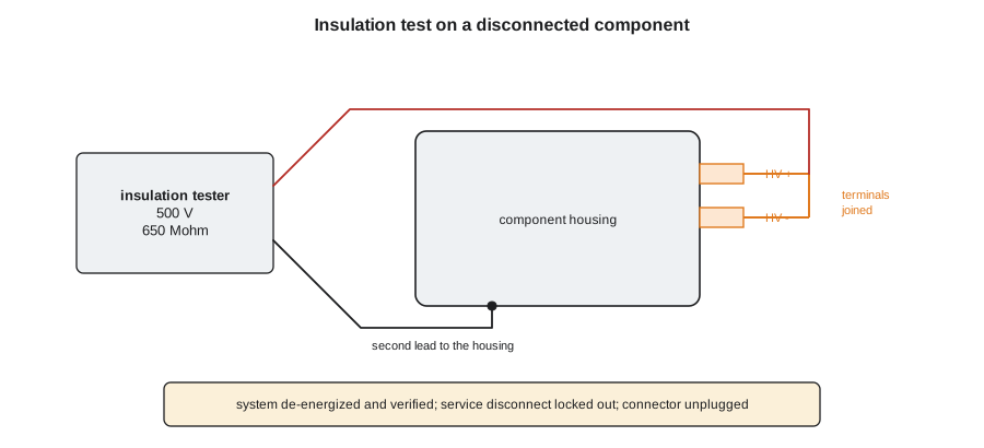
An isolation code or a low isolation reading tells the technician the high-voltage system is leaking to the body somewhere; an insulation resistance test finds where. The test uses an insulation tester, which applies a high DC test voltage, usually 500 or 1,000 volts as the maker specifies, between a component's high-voltage terminals and its housing or the vehicle body, and measures the tiny current that leaks through the insulation. The result is in megohms. The test is made only on a de-energized system, with the component disconnected so that the test voltage reaches only what is being tested, and the tester discharges the component afterward. Some electronic components must not be insulation-tested at all, because the test voltage could damage them; the service information lists which can be tested and at what voltage.
Healthy components read in the hundreds or thousands of megohms. The maker gives a minimum for each, often expressed in ohms per volt or as a fixed value; a reading near the minimum, or one that falls as the test continues, shows insulation that is breaking down. Moisture in a connector, damaged cable insulation, contaminated coolant inside a component and, in electric compressors, the wrong oil are common causes.
# Insulation resistance results: compare each component with the maker's minimum
test_v = 500
results = {"coolant heater": 650.0, "heater cable": 2200.0, "electric compressor": 48.0, "rear motor windings": 1100.0}              # megohms, terminal to housing
minimum = 10.0              # megohms, from the service information
for part, megohm in results.items():
    leak_ua = test_v / (megohm * 1e6) * 1e6
print(f"{part:24} {megohm:8.1f} Mohm, leakage {leak_ua:7.3f} uA -> {'pass' if megohm >= minimum else 'FAIL: insulation breaking down'}")coolant heater 650.0 Mohm, leakage 0.769 uA -> pass heater cable 2200.0 Mohm, leakage 0.227 uA -> pass electric compressor 48.0 Mohm, leakage 10.417 uA -> pass rear motor windings 1100.0 Mohm, leakage 0.455 uA -> pass
The heater and its cable pass easily. Kiran also tests the other components the procedure allows while the system is open, as a baseline for the fleet. The compressor's reading is much lower than the others but still well above its minimum, so she records it in the van's file as a value to watch. The capstone shows what happens when a compressor's insulation falls below its minimum.
Motor, cable and battery tests
Other tests follow the same rule: de-energized and verified first. A motor's windings are checked by measuring the resistance between each pair of phases with a low-resistance meter, a milliohmmeter, because the values are a fraction of an ohm; the three readings should match within a few percent, and an imbalance points at a shorted turn or a poor connection. The windings are also insulation-tested to the housing. High-voltage cables are inspected for chafing, crushed sections and heat damage, and insulation-tested. Their connectors are inspected for corrosion, burn marks and pushed-back pins.
Battery tests are mostly read from the battery management system, not measured. Cell group voltages at rest and under load show a weak group: a group with high internal resistance sags more than the others when the vehicle accelerates and recovers more slowly. A capacity test, a full charge followed by a measured discharge, or the battery management system's own estimate gives the state of health. Opening a traction battery to replace a module is done, if at all, by a certified battery repair facility following the maker's procedure. Ridgeline does not open packs, and Bev's policy says so in writing.
# Motor winding check: phase-to-phase resistance balance (milliohms), measured with the system de-energized
pairs = {"U-V": 18.4, "V-W": 18.6, "W-U": 18.5}
avg = sum(pairs.values()) / 3
for pair, mohm in pairs.items():
    dev = (mohm - avg) / avg * 100
    print(f"phases {pair}: {mohm:5.1f} milliohm ({dev:+5.1f} percent from average)")
spread = (max(pairs.values()) - min(pairs.values())) / avg * 100
print(f"spread {spread:.1f} percent -> {'balanced' if spread <= 3 else 'unbalanced: shorted turn or poor connection'}")phases U-V: 18.4 milliohm ( -0.5 percent from average) phases V-W: 18.6 milliohm ( +0.5 percent from average) phases W-U: 18.5 milliohm ( +0.0 percent from average) spread 1.1 percent -> balanced
What a shop repairs
Ridgeline's high-voltage policy, which Bev wrote with Marty and Dale, divides the work. The shop diagnoses all systems with the scan tool and the tests the maker allows. It replaces complete high-voltage components such as cables, coolant heaters, compressors, onboard chargers and drive units, following the maker's procedures and using the maker's parts, and it performs the software, learning and calibration steps that follow. It does not open traction battery packs, repair inverters internally, modify or reprogram battery management systems outside the maker's tools and procedures, or bypass any interlock, isolation monitor or safety function. Warranty and recall work goes to the maker's dealers, as the van's coolant heater did.
Documenting high-voltage work
Every high-voltage job leaves a written record: the codes and data before and after, who was the qualified person and who was the observer, the times of de-energizing, lockout and verification, each measurement with its value and the instrument used, the parts replaced and their part numbers, the torque values, the insulation test results and the final checks. For the van, Kiran's record also notes that the fault was a connector not fully latched after the dealer's recall repair, with photos of the unlatched secondary lock, so that the leasing company can take it up with the dealer.
With the connector seated, the components tested and the system re-energized by the procedure, the van goes ready on the first try, the interlock code clears and stays clear through three cold starts over the next two days, and Marcus is back on his route by Wednesday afternoon.
Worked problem
Choosing the next test
A hybrid will not become ready. The 12 volt battery is good, the interlock reads closed, there is no crash event, and the battery is at 68 °F. The battery management system reports isolation resistance of 6 kilohms on the negative side. What is the next step?
Show solution
- The start-up checks pass up to the isolation check, which fails.
- 6 kilohms is far below any maker's minimum for a 200 to 400 volt system.
- The next step is to de-energize the system following the maker's procedure, then disconnect and insulation-test each component and cable to find the leak.
Answer: De-energize and verify, then insulation-test components and cables one at a time to find where the system is leaking to the body.
Common mistakes
MistakeSkipping the 12 volt battery on a no-ready complaint.
InsteadTest it first; it is the most common cause.
MistakeJumpering an interlock to see if the vehicle will start.
InsteadNever bypass a safety circuit; find and fix the open point.
MistakeInsulation-testing a component that the maker says must not be tested.
InsteadCheck the service information for which parts can be tested and at what voltage.
MistakeTesting insulation with the component still connected.
InsteadDisconnect it so the test voltage reaches only that component.
MistakeIgnoring recent repairs by others.
InsteadAsk what was done recently; a disturbed connector is a common cause.
Summary and key terms
- The diagnostic strategy is the same; high-voltage tests come after de-energizing and verification.
- The 12 volt battery is the first check on any no-ready complaint.
- Several modules store codes and detailed data for the high-voltage system; generic codes are in the P0A to P0D ranges.
- The start-up sequence checks the 12 volt supply, interlock, isolation, crash signal, battery condition, precharge and contactors.
- The interlock loop runs through every high-voltage connector and must never be bypassed.
- Insulation testing at 500 or 1,000 V finds where a de-energized, disconnected component leaks to its housing.
- Shops replace complete components with the maker's procedures; packs and inverters are not opened.
- No-ready condition
- An electrified vehicle that will not enable its high-voltage system to drive.
- High-voltage interlock loop
- A low-voltage circuit through every high-voltage connector that keeps the contactors open if any is unplugged.
- Insulation tester
- An instrument that applies a high test voltage to measure insulation resistance in megohms.
- Milliohmmeter
- A meter for measuring very low resistances, such as motor windings.
- Secondary lock
- A second latch on a connector that confirms it is fully engaged.
- Isolation code
- A fault code set when the high-voltage system's isolation from the body falls too low.
Practice problems
Work each problem on paper first, then reveal the answer to check.
What is the first check on a no-ready complaint?
Show answer
The 12 volt battery.
What does an open interlock loop do?
Show answer
It keeps the contactors from closing.
At what test voltages are insulation tests usually made?
Show answer
500 or 1,000 V, as the maker specifies.
What caused the van's no-ready condition?
Show answer
The coolant heater's connector was not fully latched after a recall repair, so its interlock was open.
Lesson quiz · 5 questions
Score 60% or more to complete this lesson.
Create a free account to save your progress, take quizzes and earn a certificate.