
ARCH-400 · Lesson 6 of 12 · 22 min
Systems integration
Adaeze opens the week-five session with a drawing nobody else at the table has seen before: a section through the whole building in which the architecture has been drawn in faint lines and every service in a strong one. Ducts are blue, pipes green, electrical risers orange, sprinkler mains red. 'This is the building I'm designing,' she says. 'Yours is the faint one.' The drawing shows at a glance where the systems run, where they cross, and where they have nowhere to go. It also shows that every vertical service in the tower, eighty-odd stacks, ducts and risers, must somehow pass through the clinic on its way to the ground.
Systems as space
Mechanical, electrical, plumbing and fire protection systems take up space in three ways: in plant rooms where equipment sits, in vertical shafts that carry services between floors, and in horizontal zones, usually ceilings, where services run across each floor. In a simple building these can be found late, by squeezing. In a building like Marlow Station, with three users whose systems are different and a structure that has been carefully aligned, they must be planned with the structure and the plans, because each one competes for the same space. Kofi Mensah, the mechanical engineer who advised the students in third year, tells them that in his experience the commonest reason a mixed-use building is late and over budget is that its services were designed after its floors.
The team starts with the systems strategy for each user, agreed in the big room. All three share an all-electric source: air-to-water heat pumps on the tower roof, with thermal storage tanks, producing warm water for heating and domestic hot water and chilled water for cooling. A heat recovery chiller in the podium's mechanical room moves heat from where there is too much to where it is needed: from the clinic, whose exam rooms, lights and equipment need cooling much of the year, and from the café's refrigeration, to the homes' hot water. Each user then has its own distribution, metered separately so that each partner pays for what it uses.
The homes have four-pipe fan coils in each home and an energy recovery ventilator in each home, with its intake and exhaust in the window recesses, as in the mixed-use building the students studied in third year. The clinic has a dedicated outdoor air unit with energy recovery, serving the exam rooms through a variable air volume system, with higher filtration for its waiting areas and separate exhaust for its procedure rooms. The transit hall has a radiant floor, vestibules at its doors, air curtains and a small ventilation unit controlled by carbon dioxide sensors, because its occupancy swings from a few people to two hundred in minutes. Ines Carvalho, who taught the students' environmental systems course, reviews the strategy and asks why the hall is not simply left as a cool, sheltered room. Adaeze answers that the brief asks for a heated hall, and that the doors are the problem, not the temperature; the vestibules and air curtains are where the energy is saved.
Plant rooms
The team places the plant where it serves best and harms least. The heat pumps and tanks go on the tower roof, about 4,850 ft² behind an acoustic screen, where they have outdoor air and no neighbors above them. The clinic's air handling unit goes on the east end of the clinic's upper floor, in about 1,940 ft², close to the rooms it serves, with its outdoor air intake on the Marlow Street side, far from the bus stop's exhaust and the lane's garbage trucks. The electrical vault, the main switchboard, the water entry and the sprinkler room go on the ground floor along the lane, in about 3,230 ft², where the utility and the fire department can reach them.
Rafael raises the question of the outage rooms. The brief asks for a warm, lit room for each user during a power outage: the housing amenity room, the clinic's group room and a part of the transit hall. Each needs heat, light, outlets and ventilation from a protected circuit, and the clinic's medication refrigerators need power for days, not hours. The team chooses a battery in the electrical room, charged by solar panels on the podium roof and the tower's south face, sized to keep the three outage rooms and the refrigerators going for at least a day, with a connection for a portable generator for longer outages. The life safety systems, the emergency lighting, the fire alarm, the fire pump if one is needed, the stair pressurization and the firefighters' elevator, are on their own emergency supply as the code requires.
Shafts
In the tower, each home's bathroom and kitchen need drainage, vent, water and exhaust stacks. Back-to-back bathrooms can share a stack, and Ingrid has already arranged the plans so that each pair of homes on either side of the corridor has its bathrooms against a shared wall. The main mechanical riser, which carries the heating and cooling water between the roof plant and the floors, runs in the west core. The electrical and telecom risers run in the east core. The sprinkler and standpipe mains run in the stairs. The script below estimates the area these shafts take on each housing floor and compares two ways of bringing the stacks down through the clinic.
# Space for services: shafts on the housing floors and how stacks pass through the clinic
homes_per_floor = 12
stack_per_home = 6.5                  # ft2 per home for plumbing, exhaust and ventilation stacks
riser = {"main mechanical riser": 43, "electrical room stack": 27, "telecom": 11, "sprinkler and standpipe": 11}
floor_gross = 9050
per_floor = homes_per_floor * stack_per_home + sum(riser.values())
print(f"shafts per housing floor {per_floor:.1f} ft2 = {per_floor / floor_gross:.1%} of the floor")
offset_cost = 18000                      # dollars per stack per offset, both floors of the clinic
stacks = homes_per_floor // 2           # back-to-back bathrooms share a stack
for case, aligned in (("stacks offset at the clinic", 0), ("stacks aligned with clinic corridor walls", stacks - 1)):
    off = stacks - aligned
    print(f"{case:<44} {off:2d} offsets, about {off * offset_cost:,} dollars")
plant = {"roof heat pumps and tanks": 4850, "ground floor electrical and water": 3230, "clinic air handling (level 3)": 1940}
print("plant: " + ", ".join(f"{k} {v:,} ft2" for k, v in plant.items()))
print(f"total services space {sum(plant.values()) + per_floor * 8:,.0f} ft2 of {128150:,} gross")shafts per housing floor 170.0 ft2 = 1.9% of the floor stacks offset at the clinic 6 offsets, about 108,000 dollars stacks aligned with clinic corridor walls 1 offsets, about 18,000 dollars plant: roof heat pumps and tanks 4,850 ft2, ground floor electrical and water 3,230 ft2, clinic air handling (level 3) 1,940 ft2 total services space 11,380 ft2 of 128,150 gross
On each housing floor the shafts take only about 2% of the floor, which is typical. The problem is not their area but their route. If the tower's stacks come down wherever the homes' bathrooms happen to be, they arrive in the clinic in the middle of exam rooms and must be offset sideways in the clinic's ceilings to a wall where they can continue down. Each offset costs money, takes ceiling space and adds bends where drains can block. If instead the homes' wet walls are placed on the column lines that bound the clinic's corridors, the stacks can drop straight through the clinic inside the corridor walls. Ingrid moves six pairs of bathrooms by a few hundred millimeters, and five of the six offsets disappear.
Tomasz adds a structural reason to like the result. In the post-tensioned floors, every penetration must avoid the tendons, so a stack that drops straight through every floor in the same place can be planned once and the tendons laid around it. A stack that wanders is a set of different penetrations, each a chance for a cut tendon.
Ceilings and floor heights
The horizontal zones are set by the floor-to-floor heights fixed in the structural session. Adaeze draws a section through each type of floor, showing the depth of the structure, the depth of the services zone and the ceiling height that remains.
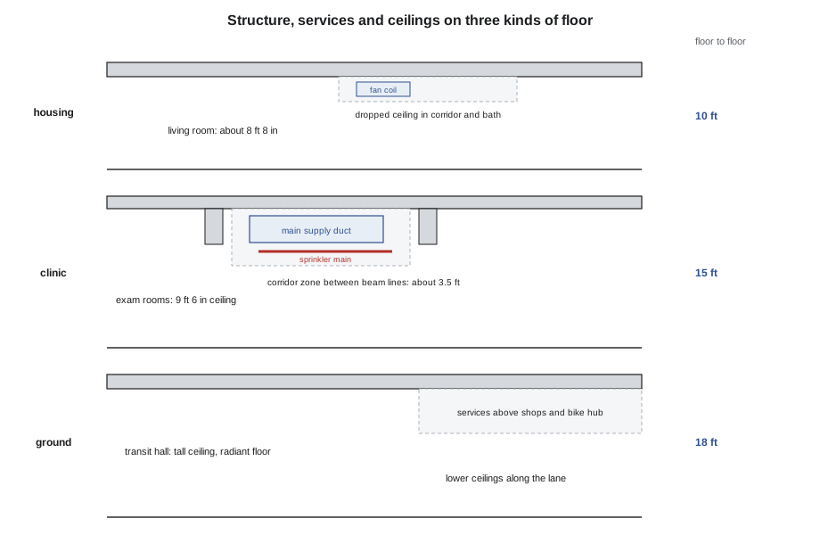
On the housing floors, the homes' living rooms have the full height under the structure, about 8 feet 8 inches, and the ceilings drop only in the corridors, the bathrooms and the entries, where the fan coils and the short ducts to the energy recovery ventilators run. On the clinic floors, the 15 foot floor-to-floor leaves a services zone of about 3.5 feet above the corridor ceilings for the main ducts, and lets the exam rooms have ceilings of 9 feet 6 inches. On the ground floor, the hall's ceiling is high and the services run above the shops and the bike hub along the lane, where the ceilings can be lower. Mensah checks the clinic's main duct size against the services zone and finds it fits, with about 6 inches to spare, if the duct runs flat and wide in the corridor between two beam lines rather than crossing them.
The team records a rule from the session: main ducts and pipes run parallel to the beams, in the zones between beam lines; only branches cross the beams, and only through openings Tomasz has approved. The rule takes thirty seconds to state and saves, Mensah says, about half the clashes he usually finds in a model.
Fire protection and the high building
Danielle Roy, the fire protection engineer, joins the end of the session. At about 128 feet to its top floor, the tower is a high-rise under the code, which brings extra measures: smokeproof or pressurized stairs, a fire command center at the main entrance, a fire service access elevator, standby and emergency power, and emergency responder radio coverage throughout. The whole building will be sprinklered, with standpipes in both stairs. The sprinkler room on the lane needs a connection for the fire department on the street, and Roy asks Hamid to make sure the fire trucks can reach it without blocking the bus stop.
Roy also notes a coordination question that has defeated many mixed-use buildings: the fire separations between the transit hall, the clinic and the homes. Every duct, pipe and cable that crosses a fire separation needs a fire damper or a tested firestop system. A building with three users stacked on top of one another has a great many crossings. She asks the team to show each separation on the services drawings, and to keep the number of crossings as small as possible by giving each user its own risers in its own part of the building. The team's decision to meter each user separately helps: separate meters encourage separate risers.
Worked problem
Fitting the clinic's main duct
The clinic's main supply duct must carry about 5,100 cfm. At a velocity of about 1,200 feet per minute, what cross-sectional area does it need, and will a flat duct of 40 by 16 inches fit the services zone?
Show solution
- Area = flow / velocity: 5,100 / 1,200 = 4.25 ft².
- A flat duct of 40 × 16 / 144 = 4.4 ft² provides it.
- With insulation and hangers, the duct needs about 20 inches of height; the services zone above the corridor ceiling is about 3.5 feet.
- That leaves room for the sprinkler main and cable trays alongside, if the duct runs between beam lines.
Answer: Yes: the flat duct fits the zone with room for sprinkler mains and cable trays beside it.
Exercise 6: systems integration
- Agree a systems strategy for each user, and locate the plant rooms, the shafts and the main horizontal zones.
- Trace every vertical service from the roof to the ground, and show how stacks pass through any floors below the ones they serve.
- Draw a section through each type of floor showing structure, services and ceiling height, and check the main ducts fit.
- Show the fire separations between users and count the services that cross them.
Self-check
- Does every stack in the tower reach the ground without an offset you could avoid?
- Do main ducts and pipes run parallel to the beams?
- Have you planned the outage rooms and the life safety systems on protected supplies?
Mensah closes the session with a reminder about maintenance. Every piece of equipment the team has placed must be reachable, removable and replaceable without demolishing anything. The heat pumps on the roof need a route for a crane or a lift; the clinic's air handling unit needs a door large enough for its largest section; the battery needs ventilation and a clear path for its replacement in about fifteen years. Adaeze adds a column to her equipment schedule for the replacement route of each item.
Common mistakes
MistakeDesigning the floors and finding room for services later.
InsteadPlan plant, shafts and ceiling zones with the structure and the plans.
MistakeLetting stacks fall wherever the bathrooms are.
InsteadAlign wet walls with the floors below so stacks drop straight.
MistakeRunning main ducts across the beams.
InsteadRun them parallel to the beams, between beam lines, and cross only with branches.
MistakeSharing risers among users with different hours and owners.
InsteadGive each user its own risers and meters, which also reduces fire separation crossings.
MistakeTreating outage power as an afterthought.
InsteadSize the battery, solar panels and protected circuits for the rooms and equipment that must keep working.
Summary and key terms
- Systems need space in plant rooms, shafts and horizontal zones, and in a mixed building these must be planned with the structure and the plans.
- All three users share roof heat pumps and a heat recovery chiller, with separate distribution and metering for each.
- Aligning the homes' wet walls with the clinic's corridor walls removed five of six stack offsets.
- Floor sections show that the clinic's main ducts fit above its corridors if they run between beam lines.
- The tower's height brings high-rise fire protection measures, and each fire separation between users must be shown and its crossings minimized.
- Plant room
- A room for the main mechanical or electrical equipment of a building.
- Shaft
- A vertical enclosed space that carries services between floors.
- Heat recovery chiller
- A machine that cools one part of a building and delivers the heat removed to another.
- Stack offset
- A sideways shift in a vertical drain, vent or duct between floors.
- Firestop system
- A tested assembly that seals a penetration through a fire separation.
Practice problems
Work each problem on paper first, then reveal the answer to check.
Twelve homes per floor, each needing 6.5 ft² of stacks, plus 92 ft² of risers. What area of shafts per floor?
Show answer
12 × 6.5 + 92 = 170 ft².
What share of a 9,050 ft² floor is that?
Show answer
About 1.9%.
A duct carries 5,100 cfm at 1,200 feet per minute. What area does it need?
Show answer
4.25 ft².
Why place the clinic's air intake on Marlow Street?
Show answer
Away from the bus stop's exhaust and the lane's garbage trucks.
What powers the outage rooms?
Show answer
A battery charged by solar panels, with a connection for a portable generator.
Why do separate meters help reduce fire separation crossings?
Show answer
They encourage separate risers for each user in its own part of the building.
Lesson quiz · 5 questions
Score 60% or more to complete this lesson.
Create a free account to save your progress, take quizzes and earn a certificate.