
ARCH-230 · Lesson 3 of 12 · 23 min
Reactions and free-body diagrams
Szymańska opens the third class by putting a ruler across two coffee mugs and a pencil eraser on top of it. She pushes the eraser along the ruler from one mug toward the other and asks the students what each mug feels. Joon-ho says the nearer mug takes more. Ingrid says the two shares must always add up to the eraser's weight. Then Szymańska slides the ruler so that one end hangs well past a mug and puts the eraser on the overhanging end. The far end of the ruler lifts off its mug. 'Now the far mug is useless,' she says, 'unless it can hold the ruler down. Today we find out, with numbers, what every support has to do.'
Supports and the reactions they provide
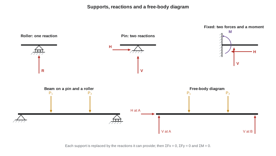
A structure stands because its supports push back on it. The forces that supports apply are called reactions. What a support can push back with depends on how it is built, and engineers describe supports by an idealized model of the movements they prevent. The three basic models in a plane are the roller, the pin and the fixed support.
- A roller prevents movement in one direction only, perpendicular to the surface it rests on, and provides one reaction force in that direction. It allows the member to slide along the surface and to rotate. A beam resting on a bearing pad that lets it expand with temperature behaves like a roller.
- A pin prevents movement in any direction but allows rotation. It provides two reaction components, usually one horizontal and one vertical. A beam bolted to a column through a simple shear connection behaves approximately like a pin.
- A fixed support prevents movement in any direction and also prevents rotation. It provides two force components and a moment. A steel post welded to a heavy base plate and anchored into a large footing, or a concrete column cast monolithically with its foundation, behaves approximately like a fixed support.
Real connections fall between these ideals. A bolted beam-to-column connection resists a little moment; a column base plate allows a little rotation. Engineers choose the model that is closest to reality and on the safe side, and then detail the connection so that it behaves as assumed. An architect who changes a connection detail, for example by welding a beam into a wall that the engineer assumed was a simple bearing, can change the forces in the whole structure. Szymańska advises: 'When you draw a connection, ask your engineer whether it is a pin or a fixed joint. The answer changes the shape of the building.'
Drawing a free-body diagram
A free-body diagram is a sketch of a structure, or a piece of one, cut free from everything around it, with every force that acts on it drawn as an arrow. It is the most important drawing in structural analysis, and every calculation in this course starts with one. Szymańska teaches it as a five-step routine.
- Isolate the body. Draw only the beam, joint, column or frame you are studying, with nothing attached to it.
- Draw the applied loads: point loads as single arrows, distributed loads as rows of arrows with their intensity labeled, and applied moments as curved arrows.
- Replace each support with the reactions it can provide, drawn as arrows in an assumed direction. If the assumption is wrong, the answer will simply come out negative.
- Label all dimensions needed for moments, and mark the unknowns.
- Write the three equations of equilibrium and solve. Take moments about a point where several unknowns act, so that they drop out of the equation.
The order matters less than the habit of drawing every force. Most errors in statics come from a forgotten force: a reaction left out, the self-weight of a member ignored, a horizontal component of an inclined load dropped. A complete free-body diagram makes such omissions visible.
A simply supported beam
A beam with a pin at one end and a roller at the other is called simply supported. It has three unknown reactions: a horizontal and a vertical force at the pin, and a vertical force at the roller. If all the loads are vertical, the horizontal reaction is zero, and the two vertical reactions can be found by taking moments about each support in turn. For a beam of span L carrying a point load P at a distance a from the left support, moments about the left support give the right reaction as P times a divided by L, and the left reaction is whatever remains.
This is the ruler and the eraser in symbols: the nearer support takes the larger share, in proportion to the distance to the other support. A uniform load w over the whole span gives equal reactions of wL/2. When several loads act, the reactions from each load can be added, because the equations are linear; engineers call this superposition. Before solving any problem, Szymańska asks the students to guess the answer: a load near the left support must give a large left reaction, and a symmetrical load must give equal reactions. An answer that contradicts the guess is a signal to check the arithmetic.
Overhangs, uplift and stability
When a beam extends past a support, the overhanging part, called a cantilever, tips the beam about that support. A load on the cantilever pushes down on the nearer support more than its own weight and pulls up on the far support. If the backspan is short or lightly loaded, the far reaction becomes negative: the beam would lift off unless it is held down. Holding down a beam needs a connection that can resist tension, such as anchor bolts or a strap, and enough weight or foundation below to keep the anchor in place.
Uplift appears in many building elements: the back end of a cantilevered canopy, the windward column of a braced frame, a light roof under wind suction, and the heel of a retaining wall. Codes check uplift and overturning with a special load combination in which the dead load is factored down, because its weight is helping, 0.9D with the full wind load. Using the full dead load in such a check would overstate the safety of the structure.
A structure must also be geometrically stable. Three reactions are necessary for a rigid body in a plane, but they must be arranged well: three parallel reactions cannot resist a sideways push, and three reactions whose lines all pass through one point cannot resist rotation about that point. A beam resting on two rollers will slide away under the slightest horizontal force. Recognizing such mechanisms on a drawing is a skill worth more than any calculation.
# Reactions for the commons entrance canopy: back support A at the wall, front post B, overhang past B
def reactions(span, total, w, point, at):
    """Supports at x = 0 (A) and x = span (B); beam length total; uniform load w over the whole length;
    point load at position at. Returns (RA, RB) from moments about A and vertical equilibrium."""
    W = w * total
    RB = (W * total / 2 + point * at) / span
    RA = W + point - RB
    return RA, RB

span, total = 13, 20           # backspan and full length (ft)
w, P = 0.4, 1.1                        # factored uniform load (kip/ft) and sign at the tip (kips)
RA, RB = reactions(span, total, w, P, total)
print(f"Backspan {span} ft, overhang {total - span} ft: RA = {RA:.2f} kips, RB = {RB:.2f} kips")
print(f"Check: RA + RB = {RA + RB:.2f}; total load = {w * total + P:.2f} kips")

# Uplift check with dead load only on the backspan factored down and full load on the overhang
for over in (3, 7, 8, 10):
    total = span + over
    W_back = 0.9 * 0.16 * span                 # 0.9 x dead load on the backspan
    W_over = w * over                          # full factored load on the overhang
    RB = (W_back * span / 2 + W_over * (span + over / 2) + P * total) / span
    RA = W_back + W_over + P - RB
    tag = "holds down" if RA < 0 else "bears"
print(f" overhang {over:>4} ft: RA = {RA:7.2f} kips ({tag}), RB = {RB:6.2f} kips")Backspan 13 ft, overhang 7 ft: RA = 1.25 kips, RB = 7.85 kips Check: RA + RB = 9.10; total load = 9.10 kips overhang 3 ft: RA = 0.54 kips (bears), RB = 3.63 kips overhang 7 ft: RA = -0.41 kips (holds down), RB = 6.18 kips overhang 8 ft: RA = -0.73 kips (holds down), RB = 6.90 kips overhang 10 ft: RA = -1.45 kips (holds down), RB = 8.42 kips
The first result is the canopy as Callum drew it: the front post takes 7.85 kips and the back support at the wall 1.25 kips. Both reactions push up, so the canopy simply bears on its supports. The second part of the script repeats the check with only part of the dead load on the backspan, as the uplift combination requires, while the overhang carries its full load. As the overhang grows, the back reaction shrinks and then turns negative; at Callum's own overhang it is already slightly negative, so the back of the canopy must be held down. Callum had planned to rest the back of the canopy beam on a simple bearing plate on the wall. The calculation shows that the back end must be bolted down into the wall structure, and that the wall and its footing must be heavy enough, or anchored well enough, to hold the beam down.
Cantilevers and fixed supports
A cantilever with a fixed support at one end and nothing at the other is held entirely by its support, which must provide a vertical force equal to the total load and a moment equal to the moment of the loads about the support. A cantilever of length L with a point load P at its tip has a support reaction of P and a support moment of P times L; with a uniform load w along its length, the reaction is wL and the moment wL²/2. Cantilevers are expensive in moment: a point load at the tip of a cantilever produces four times the maximum moment of the same load at the middle of a simply supported beam of the same length.
Architects love cantilevers for their drama: the balcony that floats, the roof that reaches out over a terrace, the upper floor that hangs over the entrance. Szymańska does not discourage them, but she asks the students to always show on their drawings where the backspan or fixed support is, and to make it large enough. 'A cantilever is a seesaw,' she says. 'Show me the other end.'
Worked problem
Overturning of the sign wall
Ingrid revises the warming-hut sign as a freestanding concrete wall 8 ft tall, 10 ft long and 8 in thick, on a footing 4 ft wide and 16 in deep. Wind pushes on the face of the wall with a pressure of 19 psf. Does the wall tip over about the toe of the footing? Use the dead load factored at 0.9 and the wind load factored as the code requires.
Show solution
- Wind force: 19 × 8 × 10 = 1,520 lb, acting at mid-height of the wall, 4 ft + 16 in = 5.33 ft above the base of the footing.
- Factored wind: 1.0 × 1,520 = 1,520 lb. Overturning moment about the toe: 1,520 × 5.33 = 8,100 lb-ft.
- Weight of the wall: 0.67 × 8 × 10 × 150 = 8,000 lb; weight of the footing: 4 × 1.33 × 10 × 150 = 8,000 lb.
- Both weights act at the middle of the footing, 2 ft from the toe, so the factored resisting moment is 0.9 × 16,000 × 2 = 28,800 lb-ft.
- The resisting moment is about 3.6 times the overturning moment, so the wall does not tip.
- The soil under the toe must still carry the concentrated pressure, which the engineer checks separately.
Answer: The wall is stable: the factored resisting moment of about 28,800 lb-ft comfortably exceeds the overturning moment of about 8,100 lb-ft.
Thinking with free bodies
Free-body diagrams are not only for whole beams. They can be drawn for a single joint in a truss, which Lesson 4 uses; for a slice of a beam, which Lesson 6 uses to find shear and moment; for a column with all the floors above it, which Lesson 9 uses to trace load paths; and for a whole building pushed by wind, to see how the footings must hold it down. The same three equations apply each time. Szymańska shows a photograph of a stair that hangs from the floor above on steel rods and asks the students to draw a free body of one tread, then of the whole stair, then of the floor beam the rods hang from. By the end of the exercise they have traced the weight of a person on the stair to the columns of the building.
She also shows how free bodies help in design. When Wren proposes a deep cantilevered window seat for the library, Szymańska draws its free body on the whiteboard: the weight of three readers at the tip, the moment at the wall, and the pair of forces in the floor structure that must resist it. Wren sees that the moment can be carried if the seat's structure continues back into the floor for at least as far as it projects, and redesigns the seat as a continuation of the floor panels rather than a box bolted to the wall.
Exercise 3: reactions
- Draw free-body diagrams for three elements in your studio project: a simply supported beam, a cantilever and a column.
- Calculate the reactions of a beam with an overhang under two point loads and a uniform load, and check them with the equations of equilibrium.
- Find the overhang at which a canopy of your design begins to lift off its back support under the uplift combination.
- Check a freestanding wall or sign of your design against overturning in wind.
Self-check
- Have I drawn every reaction each support can provide, with its assumed direction?
- Did I include the self-weight of every member?
- Did my answers match my first guess about which support takes more load?
Common mistakes
MistakeLeaving a support's horizontal reaction off the diagram.
InsteadDraw all the reactions a support can provide, even if some come out as zero.
MistakeAssuming every reaction must push up.
InsteadLet the equations decide; a negative answer means the support must hold down.
MistakeUsing the full dead load when checking uplift or overturning.
InsteadUse the reduced dead load factor, because the weight is helping.
MistakeTreating a beam on two rollers as stable.
InsteadProvide at least one support that resists horizontal movement.
MistakeDrawing a cantilever with no visible backspan or fixed support.
InsteadShow where and how the cantilever is held, with enough length or strength.
Summary and key terms
- Supports provide reactions according to the movements they prevent: a roller gives one force, a pin two forces, and a fixed support two forces and a moment.
- A free-body diagram isolates a body and shows every load and reaction acting on it.
- For a simply supported beam, the reactions follow from moments about each support, with the nearer support taking the larger share of a point load.
- Overhangs and cantilevers create uplift at back supports and large moments at fixed supports; uplift is checked with a reduced dead load factor.
- A structure needs reactions that are sufficient in number and arranged so that they cannot form a mechanism.
- Reaction
- A force or moment applied to a structure by a support.
- Roller
- A support that prevents movement in one direction only.
- Pin
- A support that prevents movement in any direction but allows rotation.
- Fixed support
- A support that prevents movement and rotation.
- Free-body diagram
- A sketch of an isolated body showing all the forces on it.
- Uplift
- An upward reaction that a support must provide to hold a structure down.
Practice problems
Work each problem on paper first, then reveal the answer to check.
A simply supported beam of span 20 ft carries a point load of 3 kips at 5 ft from the left support. What are the reactions?
Show answer
Right: 3 × 5 ÷ 20 = 0.75 kips; left: 3 − 0.75 = 2.25 kips.
A cantilever 6 ft long carries a uniform load of 0.4 kip/ft. What are the support reaction and moment?
Show answer
R = 0.4 × 6 = 2.4 kips; M = 0.4 × 6² ÷ 2 = 7.2 kip-ft.
How many reactions does a fixed support provide in a plane?
Show answer
Three: two force components and a moment.
Why must the back support of a long canopy often be anchored?
Show answer
The load on the overhang tips the beam about the front support and can pull the back support upward.
Why is a beam on two rollers unstable?
Show answer
Neither support can resist a horizontal force, so the beam can slide.
Lesson quiz · 5 questions
Score 60% or more to complete this lesson.
Create a free account to save your progress, take quizzes and earn a certificate.