
ARCH-230 · Lesson 1 of 12 · 25 min
Forces and equilibrium
The structures course at the Elmhurst School of Architecture begins in a room with no computers. Marta Szymańska, the structural engineer who drew columns on tracing paper over the students' plans in Design Studio III, now teaches Structures for Architects I. She has spent twenty-five years designing schools, arenas, libraries and bridges across the prairies, and she still keeps a box of string, weights, springs and balsa sticks under her desk. On the first morning she ties a small bag of sand to the middle of a length of cord, asks Wren and Joon-ho to hold the two ends, and tells them to pull the cord perfectly straight. They pull harder and harder. The cord never straightens, the bag keeps sagging a little, and Joon-ho's knuckles turn white. 'That,' she says, 'is the most important lesson in this course. The flatter you try to make something that carries a load, the harder it has to work.'
Wren, Callum, Ingrid and Joon-ho have already met structure as an idea. In Design Studio II they learned that walls and frames make space; in Building Technology they traced loads from a roof to a footing; in Design Studio III they chose grids and estimated beam depths from rules of thumb. This course adds numbers. By the end of it they should be able to find the forces in a simple structure, size a beam or a column well enough to draw it at the right depth, and talk with an engineer about why a structure works, not just whether it does. Szymańska is clear about the purpose: 'I do not want you to replace your engineer. I want you to stop drawing things that cannot stand, and start drawing things that stand beautifully.'
What a force is
A force is a push or a pull. Every force has three properties: a magnitude, meaning how large it is; a direction, meaning which way it acts along its line of action; and a point of application, meaning where it acts on the body. Because a force has both size and direction, it is a vector, and it is drawn as an arrow whose length represents its magnitude and whose head shows its direction. Two forces of the same size acting in opposite directions on the same line cancel; two forces of the same size acting at right angles do not.
Forces are measured in newtons in the metric system and in pounds in the US customary system. A pound of force is the weight of a one-pound mass at the earth's surface. Because building forces are large, engineers often use the kip, which is one thousand pounds (a kilo-pound), roughly the weight of five or six adults. Szymańska asks the students to keep a sense of scale: a person weighs about 150 to 200 lb, a small car about 3,000 lb, and a cubic yard of concrete about 4,000 lb.
Weight is the force of gravity on a mass. In the US system the pound is used both for mass and for force, and in everyday building work the distinction rarely matters: a 94 lb bag of cement weighs 94 lb. Structural loads on buildings are mostly weights: the weight of the structure itself, of the people and furniture inside, and of snow on the roof. The others, such as wind and earthquake, act sideways, and are discussed in Lesson 2.
Components and resultants
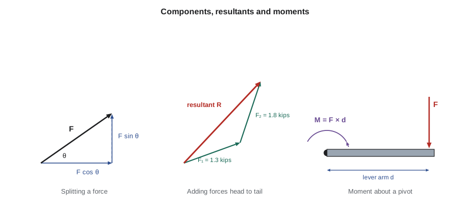
A force acting at an angle can be split into two components at right angles to each other, usually horizontal and vertical. If a force of magnitude F acts at an angle θ above the horizontal, its horizontal component is F cos θ and its vertical component is F sin θ. Splitting forces this way is the single most useful trick in structural analysis, because horizontal and vertical components can be added separately, like columns in an account book.
The reverse process combines several forces into one resultant that has the same effect. To find it, add all the horizontal components to get the total horizontal force, add all the vertical components to get the total vertical force, and combine the two totals with Pythagoras's theorem. The angle of the resultant follows from its two components. Graphically, the same result comes from drawing the force arrows head to tail; the resultant runs from the tail of the first to the head of the last. Before calculators, engineers did almost all structural analysis this way, on large sheets of paper, and the method called graphic statics is still used by designers of shells, arches and bridges because it shows the shape of the forces directly.
Moments
A force can also make a body rotate. The turning effect of a force about a point is its moment, equal to the force multiplied by the perpendicular distance from the point to the line of action of the force. That distance is called the lever arm. A door handle placed far from the hinges is easy to push because its lever arm is long; push near the hinges and the same door seems heavy. Moments are measured in pound-feet or kip-feet (lb-ft or kip-ft).
Moments have a sense, either clockwise or counterclockwise. In this course counterclockwise moments are taken as positive and clockwise moments as negative, although any consistent rule works. A pair of equal and opposite forces that do not act along the same line forms a couple; a couple produces pure rotation without any net push, and its moment is the same about every point. Turning a key, or twisting the lid off a jar, applies a couple.
Moments explain a great deal about buildings. A cantilevered balcony works because the floor behind it holds its root down against the moment of the load at the tip. A tall sign or chimney in the wind feels a moment at its base equal to the wind force times its height. A beam is mostly a device for carrying moments, as Lesson 6 shows. Szymańska gives an example everyone knows: a person weighing 180 lb standing at the end of a diving board 4 ft long applies a moment of 180 × 4 = 720 lb-ft at the root. Double the length of the board and the moment doubles, even though the person weighs the same.
The three equations of equilibrium
A structure that stands still is in equilibrium: the forces on it do not make it move or rotate. For a body in a plane, which is how most building elements are first analyzed, equilibrium means three things at once. The horizontal forces must add to zero, the vertical forces must add to zero, and the moments about any point must add to zero. These are the three equations of statics.
The equations are simple, but they are powerful because they hold for every part of a structure, not only the whole. A beam is in equilibrium; so is any piece cut from it, any joint of a truss, and any column with the floors above it. Most of the methods in the next five lessons are just ways of choosing a convenient piece and writing these three equations for it. When the number of unknown forces on a piece is three or fewer, the equations are enough to find them all; such a structure is called statically determinate. When there are more unknowns, as in a continuous beam over many supports, the structure is indeterminate and the deformations must also be considered, which is the engineer's work rather than this course's.
Newton's third law completes the picture. If a beam pushes down on a column with a certain force, the column pushes up on the beam with an equal and opposite force. A footing pushes up on a wall; the soil pushes up on the footing. Every force has a partner, and much of the art of drawing free-body diagrams, the subject of Lesson 3, is keeping track of which partner acts on which body.
The hanging sign
Szymańska turns the sandbag demonstration into a calculation. The Kestrel Point boathouse, converted into a heated warming hut in Building Technology, needs a timber sign over the path from the parking lot. Ingrid proposes to hang it from two steel cables that run up to the eaves of the hut on one side and a post on the other. The sign, its frame and a winter's worth of rime ice weigh about 270 lb. If both cables make the same angle θ with the horizontal, symmetry means each carries the same tension T. The vertical components of the two tensions must together hold up the weight, so 2T sin θ equals the weight, and the tension in each cable is the weight divided by twice the sine of the angle.
At steep angles the tension is modest; at shallow angles it grows without limit. A cable that is almost flat would need almost infinite tension to carry any weight at all, which is what Wren and Joon-ho felt in their knuckles. The script below makes the point with numbers and then solves the more realistic case where the two cables are at different angles, using the two force equations at the hook.
# Tension in the two cables that hold the warming-hut sign
import math
W = 270                      # weight of sign, frame and ice (lb)
print("Equal cable angles:")
for deg in (60, 45, 30, 15, 10, 5):
    T = W / (2 * math.sin(math.radians(deg)))
    print(f"  angle {deg:>2} deg   tension in each cable {T:8.1f} lb   ({T / W:4.1f} x the weight)")

# Unequal angles: cable 1 up to the eaves at a, cable 2 up to the post at b
a, b = math.radians(40), math.radians(25)
# sum of horizontal forces: T1 cos a = T2 cos b
# sum of vertical forces:   T1 sin a + T2 sin b = W
T2 = W / (math.sin(b) + math.cos(b) * math.tan(a))
T1 = T2 * math.cos(b) / math.cos(a)
print(f"Unequal angles 40 and 25 deg: T1 = {T1:.1f} lb, T2 = {T2:.1f} lb")
print(f"Check: horizontal {T1 * math.cos(a) - T2 * math.cos(b):+.3f}, vertical {T1 * math.sin(a) + T2 * math.sin(b) - W:+.3f}")Equal cable angles: angle 60 deg tension in each cable 155.9 lb ( 0.6 x the weight) angle 45 deg tension in each cable 190.9 lb ( 0.7 x the weight) angle 30 deg tension in each cable 270.0 lb ( 1.0 x the weight) angle 15 deg tension in each cable 521.6 lb ( 1.9 x the weight) angle 10 deg tension in each cable 777.4 lb ( 2.9 x the weight) angle 5 deg tension in each cable 1549.0 lb ( 5.7 x the weight) Unequal angles 40 and 25 deg: T1 = 270.0 lb, T2 = 228.2 lb Check: horizontal +0.000, vertical +0.000
The numbers show what Szymańska wanted them to see. At thirty degrees each cable carries exactly the weight of the sign; at ten degrees almost three times the weight; at five degrees nearly six times. The same rule governs every cable, tie and hanging structure. It explains why the main cables of a suspension bridge sag so visibly, why a clothesline pulled tight breaks its posts, and why the tension rods of a hanging canopy must be steeply inclined unless they are to become very heavy. It also explains a subtle point about the eaves of the hut: the cable that pulls on them has a horizontal component, about 207 lb in the unequal case, which the hut's wall must resist. Every inclined force in a structure brings a horizontal force with it, and someone must design for it.
Distributed loads and their resultants
Many loads are not point forces but are spread along a beam or over a floor: the weight of a slab, the snow on a roof, the books on a shelf. A load spread evenly along a beam is called a uniformly distributed load, written w and measured in pounds or kips per foot (lb/ft or kip/ft). For equilibrium calculations, a distributed load can be replaced by a single resultant equal to its total, acting at its centroid. A uniform load w over a length L has a resultant wL at the midpoint. A load that increases steadily from zero to w over a length L, such as the pressure of soil on a basement wall or the drift of snow against a parapet, has a resultant wL/2 acting at one third of the length from the heavy end.
This replacement works for finding reactions and checking overall balance, but not for finding the internal forces in a beam, which depend on how the load is actually spread. Lesson 6 returns to this distinction. Szymańska also warns about units: a distributed load per unit length times a length gives a force, and a pressure per unit area times an area gives a force. Mixing them up is the most common source of errors a thousand times too large.
Worked problem
Balancing the canoe rack
Callum designs a wall-mounted rack for the boathouse that holds two canoes on a horizontal steel arm 5 ft long, fixed to a post at one end. The canoes, with snow, weigh 80 lb each and rest at 1.5 ft and 4.5 ft from the post. The arm itself weighs 4 lb/ft. What vertical force and moment must the connection at the post provide?
Show solution
- Vertical equilibrium: the post must push up with a force equal to all the downward loads.
- Arm weight: 4 × 5 = 20 lb, acting at the middle of the arm, 2.5 ft from the post.
- Total downward load: 80 + 80 + 20 = 180 lb, so the upward reaction is 180 lb.
- Moments about the post: 80 × 1.5 + 80 × 4.5 + 20 × 2.5 = 120 + 360 + 50 = 530 lb-ft, all clockwise.
- The connection must supply an equal counterclockwise moment, usually as a pair of bolts in which the top bolt pulls and the bottom bolt pushes.
- If the bolts are 8 in apart, the force in each is about 530 × 12 ÷ 8 = 795 lb, more than four times the weight of the canoes: the price of a short lever arm.
Answer: The post must provide an upward force of 180 lb and a counterclockwise moment of about 530 lb-ft; with bolts 8 in apart the bolt forces are about 795 lb.
Equilibrium as a design idea
Equilibrium is not only a check at the end of design. It is also a way of seeing. Antoni Gaudí designed the vaults of the church crypt at the Colònia Güell near Barcelona with a hanging model of strings and small bags of shot: each string took exactly the shape that carried its loads in pure tension, and when the model was photographed and turned upside down it showed the shape that would carry the same loads in pure compression. Frei Otto later used soap films and chains for the same purpose, and contemporary engineers use computer programs that do the same thing far faster. Szymańska hangs a chain across the classroom and turns its photograph upside down on the screen. 'The chain does not know any mathematics,' she says. 'It just finds equilibrium. Our job is to find shapes that are in equilibrium on purpose.'
She closes with a warning that runs through the whole course. A drawing can show a structure that looks plausible but is not in equilibrium: a beam that lands on nothing, a canopy with no backspan, a column that stops above a window. Such drawings are not wrong in a small way; they describe buildings that cannot exist. The habit she wants is to ask of every element in every drawing: what pushes on this, and what pushes back?
Exercise 1: forces and equilibrium
- Hang a weight from a string held at two points and measure the tension with a spring scale at three different sag angles; compare with the formula.
- Resolve three forces of your own choosing into components and find their resultant by calculation and by drawing head to tail.
- Calculate the moment at the root of a cantilevered canopy over the warming hut door, for a snow load of your choice.
- Draw one element from your Design Studio III project and mark every force acting on it, with its partner force on the neighboring element.
Self-check
- Have I given every force a magnitude, a direction and a point of application?
- Have I kept units consistent, especially between loads per length and loads per area?
- Have I checked all three equations of equilibrium, not just the vertical one?
Common mistakes
MistakeTreating a force at an angle as if it acted fully vertically.
InsteadResolve it into components and use only the vertical component for vertical equilibrium.
MistakeForgetting the horizontal force that comes with every inclined cable or strut.
InsteadFind the horizontal component and show what resists it.
MistakeUsing the distance along a member instead of the perpendicular lever arm.
InsteadMeasure the lever arm at right angles to the line of action of the force.
MistakeMixing loads per length with loads per area.
InsteadMultiply a load per area by a tributary width to get a load per length, and check the units at every step.
MistakeAssuming a flat cable or tie can carry load cheaply.
InsteadRemember that tension grows as the sag angle shrinks; give cables a real sag.
Summary and key terms
- A force has magnitude, direction and point of application, and is measured in pounds and kips.
- Forces at an angle are resolved into horizontal and vertical components, which can be added separately to find a resultant.
- A moment is a force times its perpendicular lever arm; it measures the tendency to rotate.
- Equilibrium requires the horizontal forces, the vertical forces and the moments to add to zero, for the whole structure and for every part of it.
- Cables and inclined members carry load with forces that grow sharply as they flatten, and always bring horizontal forces with them.
- Force
- A push or pull with magnitude, direction and point of application.
- Resultant
- A single force with the same effect as a group of forces.
- Moment
- The turning effect of a force, equal to the force times its perpendicular lever arm.
- Couple
- Two equal, opposite and parallel forces that produce pure rotation.
- Equilibrium
- The state of a body whose forces and moments add to zero, so it does not move.
- Statically determinate
- A structure whose forces can all be found from the equations of equilibrium alone.
Practice problems
Work each problem on paper first, then reveal the answer to check.
A force of 2 kips acts at 30 degrees above the horizontal. What are its components?
Show answer
Horizontal 2 cos 30° = 1.73 kips; vertical 2 sin 30° = 1.0 kip.
A sign weighing 450 lb hangs from two cables, each at 20 degrees to the horizontal. What is the tension in each?
Show answer
T = 450 ÷ (2 × sin 20°) = 450 ÷ 0.684 = 658 lb.
What moment does a 110 lb lantern hung 3 ft out from a wall apply to its bracket?
Show answer
110 × 3 = 330 lb-ft.
A uniform load of 300 lb/ft acts on a beam 20 ft long. What is its resultant and where does it act?
Show answer
6,000 lb at the midpoint, 10 ft from either end.
Why is a structure with four unknown reactions not solvable by statics alone?
Show answer
There are only three equations of equilibrium in a plane, so a fourth unknown needs information about deformation.
Lesson quiz · 5 questions
Score 60% or more to complete this lesson.
Create a free account to save your progress, take quizzes and earn a certificate.