
ARCH-110 · Lesson 2 of 12 · 20 min
Plans
Professor Visser hands each student a slice of a cardboard model of the Kestrel Point boathouse: the model has been cut clean through, about a third of the way up its walls, and the roof lifted off. 'Look straight down,' she says. 'What you see is a plan.' Joon-ho turns the slice over in his hands. The cut walls show as thick bands of gray board, the door openings as gaps, and the window openings as thinner lines where the board steps down to the sill. Below the cut he can see the floor, a bench and the steps down to the water. 'Everything you will draw this week is a version of this,' Visser says. 'The plan is the most important drawing in architecture, because it shows how people move and how rooms relate. Le Corbusier called it the generator. If the plan is wrong, nothing else can save the building.'
What a plan is
A floor plan is a horizontal section: an imaginary cut through a building, looking straight down. By convention the cut is taken at about 4 feet above the floor, which is high enough to slice through windows and doors but below most high windows and upper cabinets. Everything the cutting plane passes through is shown as cut, with the heaviest line weight and usually a solid fill or hatch. Everything below the cut that you can see looking down, such as the floor, furniture, counters and steps going down, is drawn with lighter object lines. Things above the cut that matter, such as beams, skylights, upper cabinets and the roof edge, are drawn dashed or dotted.
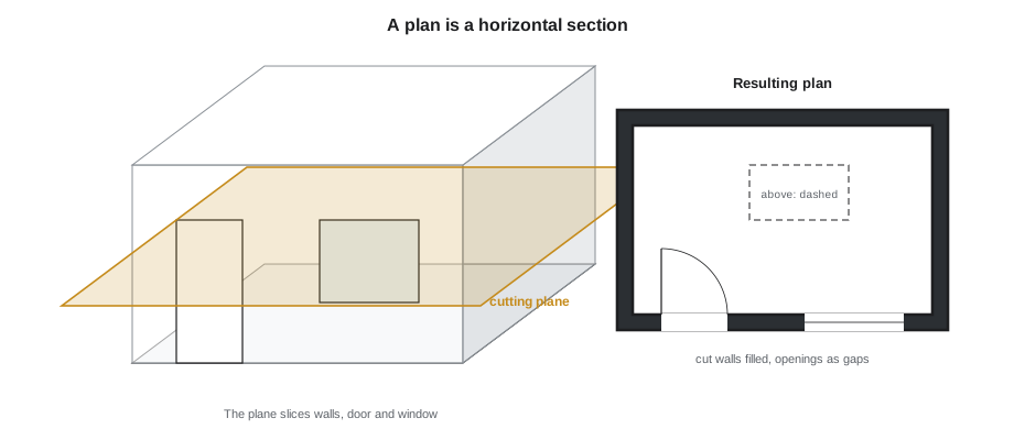
Plans are orthographic drawings. Orthographic means that every point is projected straight onto the drawing plane along parallel lines, so that sizes are true at the drawing's scale and nothing gets smaller with distance. This is what makes a plan useful for building: you can measure it. It is also what makes it abstract: no one ever sees a building this way. The French mathematician Gaspard Monge set out the geometry of this system, which he called descriptive geometry, in lectures in the 1790s; it became the basis of engineering and architectural drawing in the nineteenth century.
Kinds of plan
- Site plan: the building seen from above in its setting, showing the property boundary, roads, paths, trees, contours and north. At small scales the building is usually shown as a roof plan or a simple footprint with a heavy outline.
- Floor plan: one plan per level, showing walls, doors, windows, stairs, fixtures and rooms.
- Roof plan: the roof from above, with slopes, drains, ridges and skylights.
- Reflected ceiling plan: the ceiling as if seen in a mirror on the floor, so that it lines up with the floor plan. It shows lights, ceiling heights, bulkheads and diffusers.
- Enlarged plans: parts of a building drawn at a larger scale, such as a washroom, a stair or a kitchen.
- Diagrammatic or presentation plans: plans with color, tone and furniture that tell a story to a client or a jury rather than instruct a builder.
Drawing walls, doors and windows
Walls are the backbone of a plan. At 1/8 in = 1 ft a wall is usually two parallel lines with a fill between. At 1/4 in = 1 ft you can show the main layers, such as a stud or masonry core and the finish surfaces. At smaller scales a wall may become a single heavy line. Whatever the scale, draw walls first, at their real thickness. A common beginner's error is to draw every wall the same thickness: a 6-inch partition and a 16-inch exterior wall should look different.
Door openings are shown as a gap in the wall with the door leaf drawn open, usually at 90 degrees, and its swing drawn as a quarter circle in a light line. The swing tells you which way the door opens and how much floor it needs. Sliding doors are drawn as thin overlapping leaves in the wall, and pocket doors with the leaf partly hidden in the wall, shown dashed. Window openings are drawn as the wall stepping down to the sill: the jambs are cut, and the glass is shown as one or two thin lines in the middle of the opening, with the sill below drawn as an object line. A window that is above the cut, such as a clerestory, is shown dashed.
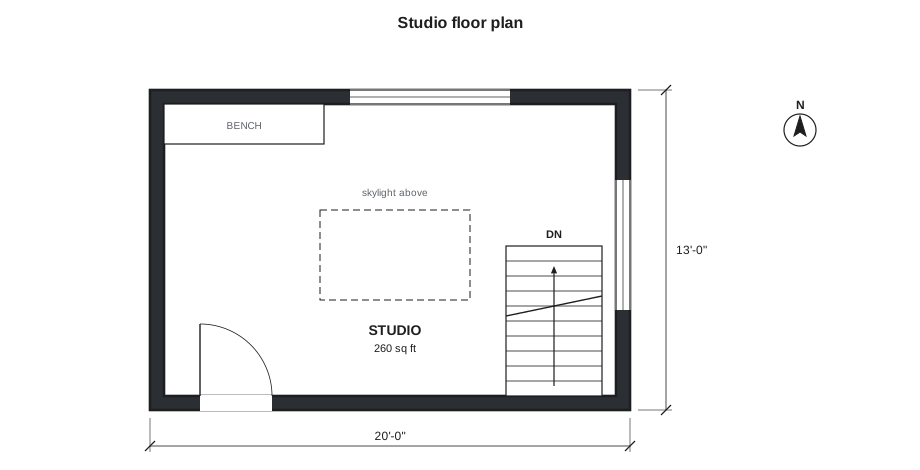
Stairs are drawn as a series of treads with a direction arrow, labeled UP or DN from the floor you are on. Because the cutting plane slices through the stair partway up, the stair is drawn with a diagonal break line where it passes the cut: below the line you see the treads, above it they continue dashed or are omitted. Ramps are drawn with an arrow and their slope written on them.
Rooms, furniture and labels
Every room gets a label, normally its name and, in technical sets, a room number keyed to a finish schedule. Many plans also give the area. Furniture is drawn lightly and simply; its job is to show that the room works and to give a sense of scale. Fixtures such as toilets, sinks and kitchen counters are drawn with their real outlines because they affect clearances and plumbing. In a design studio, furniture is also a test: if you cannot fit a bed, a desk and a door swing into a bedroom, the room is too small.
Clearances matter. In the US, the International Building Code and the 2010 ADA Standards set dimensions such as a 60-inch turning circle for a wheelchair. Show the turning circle dashed on your plans in rooms that must be accessible. You will learn the codes in detail in a later course; for now, the habit of drawing clearances is what counts.
Dimensioning a plan
Plans are dimensioned in strings. The outer string gives the overall length of the building. The next string in gives the main structural divisions, such as grid lines or the centers of walls. The innermost string locates openings and partitions. Dimensions are usually taken to the face of structure or the center line of framing, according to the office standard, and repeated as little as possible. US plans give dimensions in feet and inches.
# Room areas from a simple plan, and a check against a minimum.
rooms = [('studio', 20, 15), ('bedroom', 10, 10), ('bathroom', 8, 6), ('entry', 6, 5)]
minimum = 70
total = 0
for name, a, b in rooms:
    area = a * b
    total += area
    flag = "" if name != "bedroom" or area >= minimum else "  <- below the minimum"
    print(f"{name:<10} {a} x {b} ft = {area:.0f} sq ft{flag}")
print(f"total net area = {total:.0f} sq ft")studio 20 x 15 ft = 300 sq ft bedroom 10 x 10 ft = 100 sq ft bathroom 8 x 6 ft = 48 sq ft entry 6 x 5 ft = 30 sq ft total net area = 478 sq ft
Area calculations come straight from plans and appear in every early design report, because clients pay for area. The minimum in the script is only an example; the codes in force set their own minimums for different kinds of room, and many apply only to certain buildings.
North, orientation and the site plan
Every plan has a north arrow. On site plans it is also common to show the sun path or at least the direction of the low winter sun and the prevailing wind, because they shape where rooms and windows go. At Kestrel Point, as you saw in ARCH-100, the best views and the winter sun both come from the south, and the cold wind from the north-west. A site plan of the boathouse should show the river, the path, the cottonwoods, the bank, the flood line and the bridge, with the building drawn as a roof plan with a heavy outline.
A good site plan uses tone to separate figure from ground: the building is darkest, paths and paving are lighter, grass and planting have a soft texture, and water has its own tone. Contours are drawn as fine lines with their heights labeled, every fifth one heavier. Trees are circles drawn to the size of their canopy, with a dot for the trunk, so the reader can tell a sapling from a mature cottonwood.
Presentation plans
A plan for a client, a review or a portfolio has a different job from a plan for a builder. It tells a story: how you arrive, where the light comes in, how the rooms open to each other and to the outside. Presentation plans often use a strong black poché for walls, a light tone or texture on floors, furniture and people drawn simply, and color only for one or two ideas, such as the path of movement or the public spaces. Remove dimensions and notes that do not help the story. Ask yourself what single idea the plan must communicate, and make everything else quieter.
Many of the most famous plans in architecture are famous because they communicate one idea clearly. Mies van der Rohe's plan for the Barcelona Pavilion of 1929 is a few freestanding lines of wall and eight small crosses for the columns, and it shows at once that space flows between walls instead of being boxed into rooms. Louis Kahn's plans show served and servant spaces, the rooms people use and the spaces that hold stairs and services, as separate shapes, so you understand the building's order before you read a single label.
Worked problem
Checking a door swing and turning space
Wren's plan of the boathouse shows a 36-inch door swinging into a washroom 6 by 7 feet. Ingrid points out that the door swing and the turning circle overlap. Is that acceptable, and what are the options?
Show solution
- Draw the 60-inch turning circle in the washroom: it needs most of the floor.
- The door leaf swinging in sweeps a quarter circle of radius 36 inches into the same space.
- Codes generally allow some overlap of door swing and turning space only in specific cases, so check the code in force, but the safer design solution is to swing the door out, use a sliding door, or enlarge the room.
- Wren chooses a sliding door, which keeps the floor clear and fits the boathouse's simple character.
Answer: Drawing door swings and clearance circles at their real size reveals conflicts like this long before construction.
Exercise 2: measured plan of a real room
This exercise takes about five hours.
- Measure a real room or small building you can visit: a café, a shed, a classroom. Use a tape measure and sketch a dimensioned plan by hand on site, with every wall, door, window and fixed fixture.
- Draw it up at 1/4 in = 1 ft with proper line weights: cut walls filled, windows with glass and sill, doors with swings, fixtures drawn to size, anything above the cut dashed.
- Add a dimension string on two sides, room labels, a north arrow, a scale bar and a title block.
- Draw a second, presentation version of the same plan with poché walls, simple furniture and one idea emphasized with tone.
- Deliverable: the site sketch, the measured plan and the presentation plan on one sheet or two.
Self-critique checklist
- Are my walls drawn at their real thicknesses, and do exterior walls read heavier than partitions?
- Do door swings show the direction and the space each door needs?
- Are stairs drawn with direction arrows and a break line at the cut?
- Is everything above the cut shown dashed, and only things that matter?
- Does the presentation version communicate one clear idea?
Common mistakes
MistakeDrawing all walls the same thickness.
InsteadDraw each wall at its real thickness at the drawing scale.
MistakeLeaving out door swings.
InsteadShow every swing; it reveals clearance conflicts.
MistakeDrawing a stair without a direction arrow or break line.
InsteadLabel UP or DN and show where the cutting plane crosses the stair.
MistakeCrowding a presentation plan with dimensions and notes.
InsteadKeep presentation plans for the story; put technical information on technical plans.
Summary and key terms
- A plan is a horizontal section cut about 4 ft above the floor and viewed from above.
- Cut walls are heaviest and usually filled; things below are drawn lighter; things above are dashed.
- Doors show their swings, windows their glass and sill, stairs their direction and the cut.
- Plans are dimensioned in strings and carry room labels, a north arrow, a scale and a scale bar.
- Site plans, roof plans and reflected ceiling plans are all forms of plan with their own conventions.
- Floor plan
- A horizontal section through a building viewed from above, showing walls, openings and rooms.
- Orthographic projection
- A drawing system in which points are projected straight onto the drawing plane, so sizes are true at scale.
- Reflected ceiling plan
- A plan of the ceiling drawn as if reflected in a mirror on the floor.
- Poché
- The solid fill or tone used to show cut material in plans and sections.
- Site plan
- A plan of the building in its setting, showing boundaries, access, landscape and north.
Practice problems
Work each problem on paper first, then reveal the answer to check.
At about what height is a floor plan cut?
Show answer
About 4 ft above the floor, through doors and windows.
How is a skylight usually shown on a floor plan?
Show answer
Dashed or dotted, because it is above the cutting plane.
What is a reflected ceiling plan?
Show answer
A plan of the ceiling drawn as if seen in a mirror on the floor, so it lines up with the floor plan.
Why is a stair drawn with a break line on a plan?
Show answer
Because the cutting plane passes through it partway up; the line shows where the cut occurs.
Who set out the geometry of orthographic projection as descriptive geometry?
Show answer
Gaspard Monge, in the 1790s.
Lesson quiz · 5 questions
Score 60% or more to complete this lesson.
Create a free account to save your progress, take quizzes and earn a certificate.