
ARCH-110 · Lesson 10 of 12 · 20 min
Digital drafting
Callum opens the boathouse drawing file that a recent graduate made for the community association last year and groans. Everything is on one layer called 0. The walls are drawn at 1/4 in = 1 ft scale instead of full size, so every dimension reads wrong. Text is a dozen different sizes, some lines are white and some are a color no one can explain, and when he prints it, half the lines come out thick and half come out invisible. Professor Visser looks over his shoulder. 'The software will draw anything you tell it to,' she says. 'Drafting conventions are what make a drawing file usable by the next person. On a real project that next person might be an engineer, a contractor or you, five years from now.'
What digital drafting is
Digital drafting, often called computer-aided drafting or CAD, produces the same orthographic drawings you have made by hand, such as plans, sections, elevations and details, but as vector geometry in a computer file. Every line is stored as exact coordinates; every arc and circle by its center and radius. The drawing can be measured, copied, revised, shared and printed at any scale. Digital drafting tools have been standard in architecture since the 1990s. This lesson covers two-dimensional drafting; three-dimensional building information modeling, in which the drawings are generated from a model of building elements, is the subject of ARCH-210.
The principles of hand drafting carry over completely. Line types, line weights, scales, symbols, dimensions and title blocks are the same. What changes is how they are organized: in a CAD file, weight, color, line type and visibility are properties assigned to objects, usually through layers, and the drawing is printed to paper or PDF through settings that decide how those properties become marks.
Draw at full size in model space
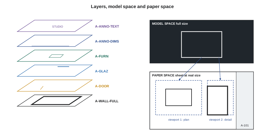
The first rule of CAD is to draw everything at full size. In model space, the drawing area where geometry lives, a wall 12 ft long is drawn 12 ft long, in real units. Scale is applied only when the drawing is placed on a sheet. This means dimensions always measure true, geometry from different drawings fits together and the same model-space drawing can be shown at 1/8 in = 1 ft on one sheet and at 1 in = 1 ft on another.
Set the drawing units before you start: feet and inches for architectural drawings in US practice, with site drawings often in decimal feet. Work with precision. Use coordinates to place points: absolute coordinates from the origin, relative coordinates from the last point and polar coordinates as a distance and an angle. Use object snaps to attach new lines exactly to endpoints, midpoints, intersections and perpendiculars of existing ones. Never eyeball a line that should meet another.
Paper space, layouts and viewports
Paper space, or a layout, represents the printed sheet at its real size, such as ARCH D at 24 by 36 in. On it you place the title block, the sheet border and one or more viewports, which are windows looking into model space at a set scale. A viewport at 1/4 in = 1 ft shows the model at that scale on the sheet. Several viewports on one layout can show the same model at different scales or with different layers visible: a plan at 1/8 in = 1 ft and an enlarged detail at 1-1/2 in = 1 ft.
Annotation, such as text, dimensions and tags, must read at the same size on paper whatever the viewport scale. Text 3/32 in high on the sheet must be 4-1/2 in high in model space for a 1/4 in = 1 ft viewport. Modern software handles this with annotative scaling, which sizes annotation automatically for each viewport; older practice set the text height by hand as the paper height multiplied by the scale factor. Either way, the result is consistent lettering across every sheet.
# Annotation sizes in model space: paper height x scale factor
paper_heights = {"notes": 0.09375, "titles": 0.1875, "room names": 0.125}
scales = {"3/4 in = 1 ft": 16, "1/4 in = 1 ft": 48, "1/8 in = 1 ft": 96, "1/16 in = 1 ft": 192}
for label, factor in scales.items():
    sizes = ", ".join(f"{k} {v * factor:g}" for k, v in paper_heights.items())
print(f"{label:>14}: {sizes} (model-space in)")3/4 in = 1 ft: notes 1.5, titles 3, room names 2 (model-space in) 1/4 in = 1 ft: notes 4.5, titles 9, room names 6 (model-space in) 1/8 in = 1 ft: notes 9, titles 18, room names 12 (model-space in) 1/16 in = 1 ft: notes 18, titles 36, room names 24 (model-space in)
The script multiplies the paper heights of notes, titles and room names by the scale factor of each common scale. At 1/8 in = 1 ft the scale factor is 96, so text 3/32 in high on paper is 9 in high in model space. Annotative scaling does the same arithmetic for you, but knowing it lets you check that a drawing is set up correctly.
Layers and the layer naming standards
Layers are the organizing system of a CAD file. Every object sits on a layer, and each layer carries default properties: color, line type, line weight and whether it prints. Layers let you turn groups of objects on and off, lock them, and give them consistent graphic treatment. A file with all its objects on one layer cannot be controlled; a file with a clear layer structure can produce plans, reflected ceiling plans, furniture plans and demolition plans from the same geometry, just by switching layers.
Layer names should follow a standard, so that everyone on a project and every consultant can read them. In North America the standard is the layer guidelines in the United States National CAD Standard, maintained by the National Institute of Building Sciences with the American Institute of Architects and the Construction Specifications Institute, and widely used in Canada as well. Internationally, ISO 13567 defines a layer structure with mandatory fields for the agent responsible, the element and the presentation, plus optional fields for status, sector, phase and scale.
An NCS layer name has up to four fields separated by hyphens. The discipline designator is one or two letters: A for architectural, S for structural, M for mechanical, E for electrical, P for plumbing, C for civil, L for landscape, I for interiors. The major group is four letters naming the building system: WALL, DOOR, GLAZ for glazing, FLOR for floor features, ROOF, FURN for furniture, ANNO for annotation. One or two optional minor groups of four letters refine it: A-WALL-FULL for full-height walls, A-WALL-PRHT for partial-height walls, A-ANNO-DIMS for dimensions, A-ANNO-TEXT for notes. An optional single-letter status field marks the phase, such as N for new, E for existing and D for demolition: A-WALL-FULL-E is an existing full-height wall.
# Parse and check NCS-style layer names
DISCIPLINES = {"A": "architectural", "S": "structural", "M": "mechanical", "E": "electrical",
               "P": "plumbing", "C": "civil", "L": "landscape", "I": "interiors"}
STATUS = {"N": "new", "E": "existing", "D": "demolition", "F": "future", "T": "temporary"}
def parse(name):
    parts = name.split("-")
    if parts[0][:1] not in DISCIPLINES or len(parts[0]) > 2 or len(parts) < 2:
        return f"{name}: bad discipline or missing major group"
    if len(parts[1]) != 4:
        return f"{name}: major group must be 4 characters"
    rest = parts[2:]
    status = STATUS.get(rest[-1]) if rest and len(rest[-1]) == 1 else None
    minors = rest[:-1] if status else rest
    if any(len(m) != 4 for m in minors) or len(minors) > 2:
        return f"{name}: minor groups must be 4 characters, at most 2"
    desc = f"{DISCIPLINES[parts[0][0]]} {parts[1]}" + "".join(f" / {m}" for m in minors)
    return f"{name}: {desc}" + (f" ({status})" if status else "")
for n in ["A-WALL-FULL", "A-WALL-FULL-E", "A-ANNO-DIMS", "E-LITE", "A-WALLS", "Layer1"]:
print(parse(n))A-WALL-FULL: architectural WALL / FULL A-WALL-FULL-E: architectural WALL / FULL (existing) A-ANNO-DIMS: architectural ANNO / DIMS E-LITE: electrical LITE A-WALLS: major group must be 4 characters Layer1: bad discipline or missing major group
The parser splits a name at the hyphens, checks the discipline, the four-character major and minor groups and an optional status letter, and prints a description. Offices use checks like this to audit drawing files before they go to consultants. Try adding your own layer names, including mistakes, to see which rules catch them.
Line weights, plot styles and color
In a CAD file, line weight can be assigned directly as a property, or it can be controlled at printing by a plot style. In the older color-dependent method, each of the 255 index colors is mapped to a pen weight in a plot style table, so that, for example, red prints with a 0.18-mm pen and yellow with a 0.35-mm pen, whatever color the lines are on screen. Named plot styles assign the mapping by name instead. Many offices now assign line weights directly on layers and print in black. Whatever the method, the office standard must be followed exactly, or drawings will print with the wrong weights.
Check plots, not screens. A drawing that looks good on a dark screen background can print as a uniform gray. Print a test sheet at full size, or make a PDF and zoom in, and check every line weight against the hierarchy: cut elements heaviest, elements beyond lighter, annotation and hatching lightest.
Blocks, references and file formats
Blocks are reusable groups of objects, such as a door, a toilet or a title block, defined once and inserted many times. If the block is redefined, every instance updates. Use blocks for anything repeated, and keep a library of standard blocks. Attributes attached to blocks store information such as a door number or a sheet title, which can be extracted into schedules.
External references, or xrefs, link one drawing file into another without copying its contents. A floor plan file can be referenced into a reflected ceiling plan, a furniture plan and the structural engineer's framing plan; when the architect changes a wall, every file that references it updates. Xrefs are the main way teams coordinate in two-dimensional CAD, and they rely on everyone drawing at full size from a shared origin.
The most common file format for CAD drawings is DWG, the native format of AutoCAD, which many other programs can read and write. DXF, the Drawing Exchange Format introduced by Autodesk in 1982, is a documented format for exchanging drawings between programs. Drawings are issued to clients, consultants and contractors as PDF, which preserves the printed appearance exactly. When you send a CAD file, include its references, fonts and plot styles, or bind the references into the file, so that it opens correctly on another computer.
Worked problem
Setting up a viewport
Joon-ho is placing the boathouse plan on an ARCH D sheet at 1/4 in = 1 ft. The boathouse is 24 ft by 16 ft. How big is the viewport on the sheet, and what text height should he use in model space for 3/32 in notes?
Show solution
- Plan size on paper: 24 ft × 1/4 in = 6 in by 16 ft × 1/4 in = 4 in.
- Allow a margin for dimensions and labels: a viewport about 9 by 7 in fits easily on the sheet.
- Model-space text height: 3/32 in × 48 = 4.5 in, unless he uses annotative scaling.
Answer: The plan occupies about 6 by 4 in on the sheet, inside a viewport of about 9 by 7 in, and notes are 4-1/2 in high in model space.
Exercise 10: a CAD drawing set
This exercise takes about seven hours.
- Draw your measured space or the boathouse in CAD at full size in model space, with the units set correctly.
- Use at least ten NCS-format layers, including walls, doors, glazing, furniture, dimensions and text, and run their names through the parser.
- Create a sheet layout with a title block, a plan viewport at 1/4 in = 1 ft and a detail viewport at 1-1/2 in = 1 ft.
- Insert doors and furniture as blocks, and reference the plan into a second file for a furniture plan.
- Plot to PDF and check the line weights at full size.
- Deliverable: the DWG or DXF files with references and the PDF sheet.
Self-critique checklist
- Is everything drawn at full size, with dimensions that measure true?
- Is every object on a properly named layer, with nothing on layer 0?
- Does text read at the same size on paper in every viewport?
- Does the PDF show the correct line-weight hierarchy?
- Will the file open correctly on someone else's computer?
Common mistakes
MistakeDrawing at scale in model space.
InsteadDraw everything at full size; apply scale only in viewports.
MistakePutting everything on one layer.
InsteadUse a standard layer structure, such as the NCS format.
MistakeJudging line weights on the screen.
InsteadCheck a plotted sheet or PDF at full size.
MistakeSending a file without its references and plot styles.
InsteadInclude or bind references, and send plot styles and fonts.
Summary and key terms
- Digital drafting produces orthographic drawings as precise vector geometry; the conventions of hand drafting still apply.
- Draw at full size in model space and apply scale through viewports in paper space.
- Annotation height in model space equals paper height times the scale factor, or is handled by annotative scaling.
- Layers organize the file; the NCS and ISO 13567 give standard layer names, such as A-WALL-FULL.
- Plot styles or layer properties control printed weights; blocks, xrefs, DWG, DXF and PDF support reuse and exchange.
- Model space
- The CAD drawing area where geometry is drawn at full size.
- Paper space
- The CAD layout representing the printed sheet at real size.
- Viewport
- A window on a layout showing model space at a set scale.
- Layer
- A named group of objects sharing properties such as color, line type and weight.
- External reference
- A drawing file linked into another so that changes update automatically.
Practice problems
Work each problem on paper first, then reveal the answer to check.
Why draw at full size in model space?
Show answer
So dimensions measure true, drawings fit together and any scale can be used on sheets.
What does A-WALL-FULL-E mean?
Show answer
Architectural, walls, full height, existing.
How high is 3/32 in text in model space for a 1/8 in = 1 ft viewport?
Show answer
9 in.
What is an xref used for?
Show answer
Linking one drawing into another so that changes update everywhere.
What is DXF?
Show answer
The Drawing Exchange Format, introduced by Autodesk in 1982 for exchanging drawings.
Lesson quiz · 5 questions
Score 60% or more to complete this lesson.
Create a free account to save your progress, take quizzes and earn a certificate.