
APT-320 · Lesson 5 of 12 · 23 min
Hydraulic hoses, fittings and components
▶ Video coming soon A video version of this lesson is on the way.
At 10:40 on Wednesday, October 14, Faisal Rahimi called the branch from the quarry. A hose on one of Kessock's wheel loaders had burst at the lift cylinder, sprayed oil across the loader arm and left the machine parked at the face. Kip Lindqvist drove out, collected the failed hose and both fittings in a bag, and came back to the hose bench. He identified the hose from the layline printed along it, matched the fittings with a seat angle gauge and a thread gauge, measured the overall length and the angle between the two elbows, and built a new assembly in twenty minutes. He was back at the quarry by 12:30. While he was there, a Kessock mechanic checking another hose for a weep ran his hand slowly along it with the engine running. Kip stopped him mid-reach and handed him a piece of cardboard. Kip's note in the binder ended: "The hose took twenty minutes. The cardboard took two seconds and was more important."
How a hydraulic system works
A hydraulic system moves power with oil under pressure. A pump driven by the engine or a motor pushes oil from a reservoir through valves to cylinders, which push or pull in a straight line, and motors, which turn. Filters keep the oil clean, a cooler removes heat, and hoses, tubes and fittings connect everything. Mobile equipment commonly runs at about 3,000 to 5,000 psi, and some systems run higher. At those pressures a small cylinder exerts a very large force.
Worked problem
Force from a hydraulic cylinder
A loader's lift cylinder has a bore of 4 in, and the system pressure is 3,000 psi. What force does the cylinder produce when extending?
Show solution
- Piston area:
- \[A = \pi \times 2^2 \approx 12.57 \text{ in}^2\]
- Force:
- \[F = 3{,}000 \times 12.57 \approx 37{,}700 \text{ lbf}\]
Answer: About 37,700 lbf, nearly 19 tons of force. A pinhole in a hose carrying that pressure releases a jet of oil that can pass through skin, which is why the cardboard matters.
Hose construction and standards
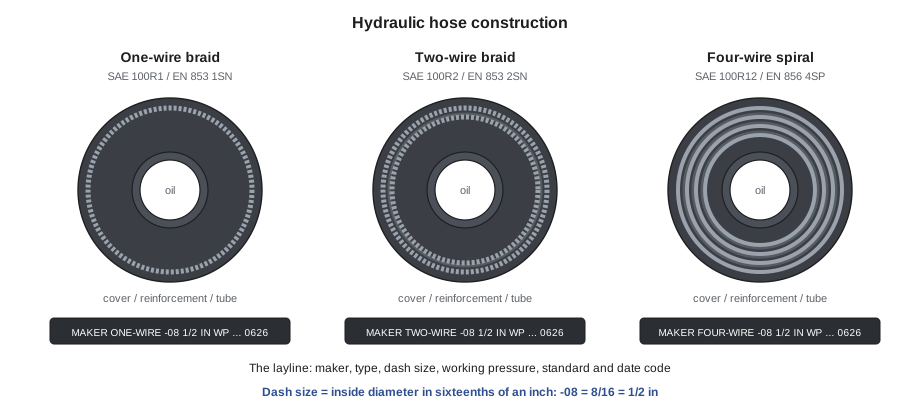
A hydraulic hose has three layers: an inner tube of oil-resistant rubber or thermoplastic, one or more layers of reinforcement, and an outer cover that resists abrasion, weather and oil. The reinforcement sets the pressure rating:
- Textile braid for low-pressure lines, such as return and suction lines.
- One-wire braid, such as SAE 100R1 and the European EN 853 1SN.
- Two-wire braid, such as SAE 100R2 and EN 853 2SN, the workhorse of mobile equipment.
- Four- and six-wire spiral, such as SAE 100R12, 100R13 and 100R15 and EN 856 4SP and 4SH, for high-pressure, high-impulse lines on excavators and loaders.
- Compact hoses, such as SAE 100R16 and 100R17, which give two-wire pressures in a smaller outside diameter and a tighter bend radius.
The SAE J517 series names hoses by construction. The newer ISO 18752 instead groups hoses by pressure class and impulse grade, so a hose is chosen by the performance it must deliver rather than how it is built. Hose makers print both on the layline, the text running along the cover: the maker, hose type, size, working pressure, standard met and a date code. The layline is the first place to look when identifying a failed hose.
Hose sizes use dash numbers: the inside diameter in sixteenths of an inch. A -08 hose has a 1/2 in inside diameter, a -12 hose 3/4 in, and a -16 hose 1 inch. Metric catalogs add a DN nominal size; DN 12 corresponds closely to -08. The inside diameter decides flow; the outside diameter, which varies with construction, decides which fittings and clamps fit.
Choosing the right hose
Hose suppliers teach the word STAMPED as a checklist for selecting a hose and its ends:
- Size: the inside diameter, and the overall length of the assembly.
- Temperature: of the oil and of the surroundings. Hoses near exhaust or turbochargers need heat-resistant covers or sleeves.
- Application: how the hose is routed, how it flexes, the bend radius, abrasion, and whether it is a suction line.
- Media: the fluid. Hydraulic oil, biodegradable fluids, water-glycol, fuel and phosphate esters each need compatible tube materials.
- Pressure: working pressure, including pressure spikes. The assembly is only as strong as its lowest-rated part.
- Ends: the fittings at each end and their orientation.
- Delivery: when the customer needs it, and any testing or documentation.
Worked problem
The weakest part sets the rating
A hose assembly uses a hose rated for 4,000 psi working pressure, a fitting at one end rated 5,000 psi and an adapter at the other end rated 3,000 psi. What is the working pressure of the assembly?
Show solution
- Compare the ratings:
- \[\min(4{,}000,\ 5{,}000,\ 3{,}000) = 3{,}000 \text{ psi}\]
Answer: 3,000 psi. If the system runs at 3,500 psi, the adapter must be replaced with a higher-rated one. The ratings here are teaching values; real ratings come from the makers' catalogs.
Identifying fittings
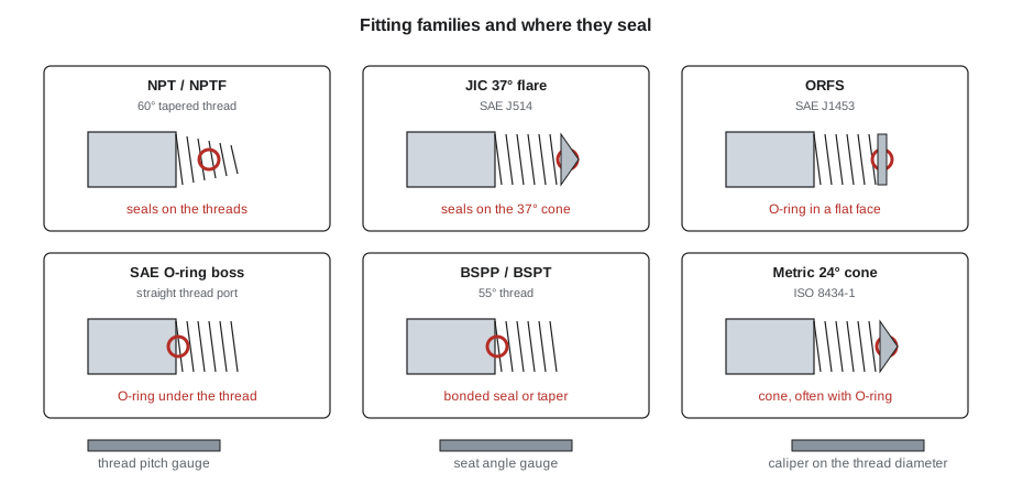
Fittings are where most identification mistakes happen, because many look alike. A fitting is identified by how it seals and its thread. The common families:
- NPT and NPTF (American pipe thread): tapered threads with a 60° thread angle that seal by the threads wedging together, usually with sealant on NPT. Common on older equipment and in industrial plumbing, but prone to leaks under vibration.
- JIC 37° flare (SAE J514): a 37° cone seat on the male end meets a matching flare on the female swivel nut. Very common on North American mobile equipment. The thread only holds the parts together; the cone seals. A 45° SAE flare used on refrigeration and fuel lines looks similar but does not seal with a 37° seat.
- O-ring face seal (ORFS) (SAE J1453): a flat face with an O-ring in a groove seals against a flat face. It resists leaks under high pressure and vibration and is standard on many modern machines.
- SAE O-ring boss (ORB) (SAE J1926 ports): a straight thread with an O-ring that seals against a chamfered port, used where fittings screw into pumps, valves and cylinders.
- BSPP and BSPT (British parallel and tapered pipe): 55° thread angle, used on equipment from Europe and Asia. BSPT is tapered like NPT but not interchangeable.
- Metric DIN 24° cone (ISO 8434-1), in light and heavy series, common on European machines, with or without an O-ring on the cone.
- Four-bolt flanges (SAE J518 Code 61 and Code 62) for large, high-pressure lines, clamped by split or one-piece flange halves. Code 62 is the higher-pressure series and has larger bolts.
To identify a fitting, the counter uses a thread pitch gauge, a seat angle gauge and a caliper. Measure the thread's outside diameter on a male thread or the inside diameter on a female, count the threads per inch or read the metric pitch, check the seat angle or the seal face, and look for an O-ring groove. For example, a -08 JIC fitting has a 3/4-16 thread (three-quarters of an inch, 16 threads per inch), while a -08 ORFS fitting has a 13/16-16 thread. Getting either wrong produces a fitting that may thread on a turn or two and then leak or strip.
Never mix families to make something fit. A JIC male into a 45° flare nut, a BSPP fitting into an SAE port, or a BSPT into NPT may hold for a while and then fail under pressure. When the old fitting is unknown, ask for the fitting itself or for photos showing the seal and threads next to a ruler.
Building a hose assembly
Many counters build hose assemblies on site, on a crimper. The steps are set by the hose and fitting maker:
- Choose a matched system. Use the hose and fittings that the maker approves together, with the maker's crimp die and crimp diameter. Mixing one maker's hose with another's fittings is a common cause of blow-offs and is not covered by either maker's warranty.
- Cut the hose square with a hose saw, and clean it. Cutting leaves rubber and wire debris inside the hose; most shops blow a foam projectile through the hose to clean it.
- Mark the insertion depth and push the fitting fully onto the hose. Some hoses must be skived (the cover trimmed back) for certain fittings; many modern systems are no-skive.
- Crimp with the specified die set and check the crimp diameter with a caliper against the maker's figure.
- Set the orientation of the two ends, called the phase angle, for elbows that must point in particular directions. Measure the old assembly's angle before cutting it apart.
- Measure the overall length from the end of one fitting's seat or face to the other, as the maker defines it, not just the cut length of the hose.
- Cap the ends, tag the assembly with its part details, and record it. Some customers require a pressure test certificate.
Failed hoses tell a story. Kip looks for abrasion on the cover from rubbing, kinks from too tight a bend, twisting from a poorly installed elbow, heat damage, blown fittings from a bad crimp, and cracked covers from age. If the old hose failed from rubbing or heat, a new hose of the same type will fail the same way unless the routing changes or a sleeve or guard is added.
Injection injuries and other hydraulic hazards
Hydraulic oil escaping through a pinhole can inject itself under the skin. Pressures far below a system's working pressure, often cited as low as about 100 psi, are enough. The wound may look like a tiny puncture and feel like a sting, but oil spreads through the tissue and can cause severe damage or loss of a finger or hand within hours. An injection injury is a surgical emergency: the person goes to hospital immediately and tells the staff it is a high-pressure injection injury, with the type of fluid.
Rules for anyone near hydraulic equipment:
- Never feel for leaks with a hand. Pass a piece of cardboard or wood along the hose, with eye protection on.
- Relieve pressure before loosening any fitting: shut down, lower attachments to the ground, and operate the controls as the maker specifies. Some systems have accumulators that hold pressure after shutdown.
- Block raised loads. Never work under an attachment held up only by hydraulics.
- Beware of hot oil and of hoses that whip when a fitting lets go.
- Use burst sleeves and guards near operator stations and walkways, where the machine maker specifies them.
Other hydraulic components
The counter also sells and identifies:
- Cylinders and seal kits: identified by bore, rod diameter, stroke, mounting style and the maker's number (Lesson 6 covers seals).
- Pumps and motors: gear, vane and piston designs, identified by their plates, shaft spline or keyway, mounting flange, rotation direction and displacement. They are often supplied remanufactured.
- Valves: control valves, relief valves, check valves and solenoid valves with their coils.
- Filters, rated by the size of particles they trap in micrometers and by beta ratio efficiency. Hydraulic cleanliness is described by an ISO 4406 code. Dirty oil is the main cause of hydraulic component failure.
- Fluids: hydraulic oils by viscosity grade, such as ISO VG 46; universal tractor fluids that serve a tractor's shared transmission and hydraulics; and biodegradable fluids. Use what the maker specifies.
- Quick couplers: agricultural couplers to ISO 5675, flat-face couplers to ISO 16028 on skid steers and compact machines, and others. Flat-face couplers keep dirt out and spill less.
Keep caps and plugs on every hose, fitting and component in stock. A pump or valve left open on a shelf collects dust that can destroy it on start-up.
Clean oil and stored hose
Two counter habits protect customers' hydraulic systems before a part is ever installed.
Clean oil. New hydraulic oil is often dirtier than a system's own oil after filtration. Cleanliness is described by an ISO 4406 code of three numbers, such as 18/16/13, each showing the number of particles in a milliliter larger than a given size; lower numbers mean cleaner oil. Many equipment makers specify a target code for their systems. The counter can help by selling oil from sealed containers, offering filter carts or pre-filtered oil where the branch has them, keeping drum and tote taps covered, and never using the same funnel or container for different fluids.
Stored hose. Bulk hose on reels and finished assemblies have a shelf life. Industry recommended practice, such as SAE J1273, gives guidance on storage and age: keep hose in a cool, dark, dry place away from ozone sources such as electric motors and welders, store it straight or loosely coiled rather than kinked, and rotate it first in, first out by the date code on the layline. Fittings are kept in their bags or bins so threads and sealing faces are not damaged, and O-rings in sealed packets away from light.
A counter that builds hoses from clean, well-stored stock, caps every assembly, and sells clean oil is protecting pumps and valves that cost many times more than the hose.
Common mistakes
MistakeFeeling along a hose for a leak with a bare hand.
InsteadUse cardboard or wood and eye protection; injection injuries are surgical emergencies.
MistakeIdentifying a fitting by eye.
InsteadUse a thread gauge, seat angle gauge and caliper, and identify the seal type.
MistakeCrimping one maker's fitting onto another maker's hose.
InsteadUse a matched hose and fitting system with the maker's dies and crimp diameter.
MistakeReplacing a rubbed-through hose with the same hose on the same route.
InsteadFix the cause: reroute, clamp, sleeve or guard.
MistakeRating an assembly by the hose alone.
InsteadThe lowest-rated component sets the assembly's working pressure.
Summary and key terms
- Hydraulic systems on machines commonly run at 3,000 to 5,000 psi, producing very large forces.
- Hoses are built with textile, braided or spiral reinforcement and named by SAE J517, EN or ISO 18752; the layline identifies them.
- Dash sizes give the inside diameter in sixteenths of an inch; STAMPED guides selection.
- Fittings are identified by seal type and thread: NPT, JIC 37°, ORFS, ORB, BSP, metric 24° cone and four-bolt flanges.
- Assemblies are built from matched systems, cleaned, crimped to specification, measured and capped; injection injuries are emergencies.
- Layline
- The printed text along a hose giving its maker, type, size, pressure and date.
- Dash size
- Hose or fitting size in sixteenths of an inch of inside diameter.
- JIC 37° flare
- A fitting that seals on a 37° cone seat, to SAE J514.
- ORFS
- O-ring face seal fitting, sealing with an O-ring on a flat face, to SAE J1453.
- Crimp diameter
- The specified outside diameter of a crimped fitting ferrule, checked with a caliper.
- Phase angle
- The angle between the two ends of a hose assembly with elbow fittings.
- Injection injury
- An injury in which fluid under pressure is forced through the skin.
Practice problems
Work each problem on paper first, then reveal the answer to check.
What inside diameter is a -12 hose?
Show answer
12 sixteenths, or 3/4 in.
A 2 in bore cylinder works at 3,000 psi. What force does it produce?
Show answer
Area ≈ 3.14 in²; 3,000 × 3.14 ≈ 9,400 lbf.
How does a JIC fitting seal?
Show answer
On its 37° cone seat; the thread only holds it together.
What should a mechanic use to look for a hydraulic leak?
Show answer
A piece of cardboard or wood, with eye protection, never a hand.
Why are hoses cleaned with a projectile after cutting?
Show answer
Cutting leaves rubber and wire debris that would contaminate the system.
Lesson quiz · 5 questions
Score 60% or more to complete this lesson.
Create a free account to save your progress, take quizzes and earn a certificate.