
AERO-499 · Lesson 9 of 12 · 23 min
Certification and safety considerations
An aircraft that cannot be certified cannot be sold to a flight school, however well it flies. Certification is therefore not a step at the end of the design but a constraint on every decision, and Rachel Oduya, the sponsor's certification mentor, has been at every design review since the concept stage. In weeks 19 to 22 Grace leads the work that turns her advice into two documents: a certification plan, which says how the Plover E2 would show that it meets every applicable requirement, and a preliminary system safety assessment, which shows that the new hazards of the electric drive have been identified and that the design makes them acceptably unlikely. Neither document can be complete in a capstone. Both can be sound in structure and honest about what remains open.
The certification basis
The certification basis is the set of rules a particular aircraft must meet. For the Plover E2 it starts with 14 CFR Part 23 at amendment 23-64, the airworthiness standard for normal category airplanes, applied at certification level 1, low speed. The rules in this standard are written as safety objectives: the aircraft must be controllable and maneuverable in all phases of flight, its structure must carry the loads it will meet with a defined margin, its powerplant installation must not create hazards, and so on. How an applicant shows compliance with each objective is set out in means of compliance, many of them consensus standards published by ASTM International and accepted by the authorities. ASTM F3338, for example, is a standard specification for the design of electric propulsion units for general aviation aircraft.
In the United States the FAA accepts consensus standards as means of compliance with Part 23 through published notices, and adds special conditions where an aircraft has novel features the rules do not address, such as an electric propulsion system and a high-voltage battery. Rachel expects the certification basis to be Part 23 at amendment 23-64, level 1, low speed, plus special conditions of that kind. For sales in Canada, Transport Canada would validate the US type certificate under the bilateral agreement between the two countries, as it did in November 2025 for the European certificate of the Velis Electro, and the team keeps a list of points where Transport Canada's expectations might differ.
Special conditions are rules written for one type when the standard does not cover a novel feature. For the Plover E2 they are expected to cover the electric propulsion unit as a whole (what counts as its failure, its ratings, its endurance and overspeed testing), the battery (thermal runaway, venting, crash protection, state of charge indication), high-voltage installation and the reserve energy requirement. Rachel points the team to published special conditions for the first certified electric airplanes, whose content shows what the authorities consider the main issues.
The certification plan
The certification plan lists every requirement in the basis, says how compliance will be shown, and says who will produce and who will approve each piece of evidence. For each requirement the method is one or more of: a statement of design or a drawing, calculation or analysis, a safety assessment, a laboratory test, a ground test on the aircraft, a flight test, an inspection, or simulation. The plan also defines the conformity process, by which the authority confirms that the article tested is built to the drawings that will be certified, and the role of delegates: in a company with design delegation, engineers holding authority from the regulator, such as a Designated Engineering Representative, can approve some compliance findings themselves.
| Area | Example requirement | Planned compliance method |
|---|---|---|
| Flight | Stall characteristics and spin recovery | Flight test, with simulator and subscale evidence in support |
| Structure | Limit and ultimate loads, utility category | Analysis, static test of the wing to ultimate load |
| Structure | Flutter | Analysis, ground vibration test, flight flutter test |
| Design | Emergency landing loads on items of mass | Analysis, static test of battery mounts |
| Powerplant | Electric propulsion unit ratings and endurance | Test of the unit to the propulsion standard, special conditions |
| Battery | Thermal runaway containment | Propagation test of a module, test of the installed enclosure |
| Systems | System safety | Functional hazard assessment, fault trees, failure modes analysis |
| Systems | Software in the battery management system and inverter | Development assurance to an agreed level |
| Operations | Energy indication and reserve | Analysis and flight test of the indication accuracy |
| Environment | Noise | Noise certification flight test |
Grace builds the plan in a spreadsheet with about 230 lines, one for each applicable requirement, and the team discovers how much of the certification effort falls on parts of the aircraft it has barely designed. The cabin, the flight controls, the avionics installation, the placards and the flight manual each have dozens of requirements. Rachel says this is normal: for a small airplane, the structural and flight test campaigns are the visible parts of certification, but the paperwork for every system, and the conformity of every test article, take most of the time.
The safety assessment process
The system safety assessment follows a sequence the aerospace industry has used for decades. A functional hazard assessment lists the aircraft's functions, asks what happens if each is lost or malfunctions, and classifies the effect by severity: catastrophic (prevents continued safe flight and landing, with likely fatalities), hazardous (large reduction in safety margins, serious injury possible), major (significant reduction in margins, discomfort or minor injury), minor, or no safety effect. Each class has a maximum allowable probability. For small single-engine airplanes, the guidance used with the older rules set limits of about 10⁻⁶ per flight hour for catastrophic failure conditions, 10⁻⁵ for hazardous and 10⁻⁴ for major, and the system safety standard accepted for the new rules keeps limits of this kind, scaled by aircraft class.
The preliminary system safety assessment then examines the proposed architecture to show that each failure condition can meet its limit, using fault tree analysis for the top-down view and failure modes and effects analysis for the bottom-up view. The final system safety assessment, done on the finished design, confirms it with the real failure rates. The capstone can do the first two steps for the propulsion system.
| Failure condition | Effect | Classification |
|---|---|---|
| Uncontained battery fire in flight | Fire threatens the occupants and the structure | Catastrophic |
| Loss of all thrust | Forced landing, as after an engine failure in a piston trainer | Hazardous (company target) |
| Partial loss of thrust | Reduced climb, return to the airfield | Major |
| Misleading energy indication | Pilot believes more energy remains than does; reserve lost | Hazardous |
| Loss of energy indication, annunciated | Pilot lands as soon as practical | Minor |
| High-voltage exposure on the ground | Electric shock to a technician or rescuer | Catastrophic (ground) |
Two classifications need explanation. The rules for single-engine airplanes accept that an engine can fail and the aircraft must glide to a landing; that is why every student practices forced landings. Loss of all thrust in the Plover E2 has the same effect and could be classed in the same way, but the team adopts a stricter company target, hazardous, because a primary trainer is flown by students, and because one reason a school would choose an electric trainer is the promise that it is more reliable than a piston engine. And the misleading energy indication is classed as hazardous because it removes the reserve without the pilot knowing. A fuel gauge in a light aircraft is notoriously inaccurate, but pilots are taught to plan fuel by time and to check it visually. An electric aircraft's state of charge cannot be seen; the pilot depends entirely on the battery management system's estimate. The team therefore requires two independent estimates of remaining energy, one from the battery management system's model and one from integrating the measured current, with a caution if they disagree.
Fault tree analysis
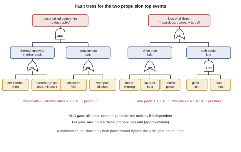
A fault tree starts from a top event and works downward through logic gates to basic events whose probabilities can be estimated. An OR gate's output occurs if any input occurs; for small probabilities its probability is close to the sum of the inputs. An AND gate's output occurs only if all inputs occur; if they are independent its probability is the product. Redundancy shows up as AND gates, and its value depends entirely on the independence of the inputs.
# Fault tree for two top events of the Plover E2 propulsion system (rates per flight hour, illustrative)
def OR(*p):
    q = 1.0
    for x in p: q *= (1 - x)
    return 1 - q
def AND(*p):
    q = 1.0
    for x in p: q *= x
    return q
T = 1.0                                   # exposure: one flight hour
# basic events
cell_internal_short = 2e-5 * T            # per pack, cell event that starts a thermal runaway
bms_misses_overcharge = 1e-4              # probability on demand
charger_overcharge = 1e-5 * T
containment_fails = 2e-3                  # probability the pack enclosure fails to contain a runaway
vent_path_blocked = 1e-3
motor_open_winding = 1e-5 * T
inverter_fault = 5e-5 * T
contactor_open = 2e-5 * T                 # per pack
pack_lost_other = 3e-5 * T                # per pack: connector, cooling, BMS trip
ctrl_power_lost = 1e-6 * T

runaway_per_pack = OR(cell_internal_short, AND(charger_overcharge, bms_misses_overcharge))
runaway_any = OR(runaway_per_pack, runaway_per_pack)
fire_uncontained = AND(runaway_any, OR(containment_fails, vent_path_blocked))
print(f'thermal runaway in either pack: {runaway_any:.2e} per hour')
print(f'uncontained battery fire (catastrophic): {fire_uncontained:.2e} per hour, target 1e-06 -> {"met" if fire_uncontained <= 1e-6 else "NOT met"}')

drive = OR(motor_open_winding, inverter_fault, ctrl_power_lost)
one_pack = OR(contactor_open, pack_lost_other)
single_pack_design = OR(drive, one_pack)                 # one large pack
two_pack_design = OR(drive, AND(one_pack, one_pack))     # two packs, either can power the motor
print(f'\nloss of all thrust, one-pack design: {single_pack_design:.2e} per hour')
print(f'loss of all thrust, two-pack design: {two_pack_design:.2e} per hour (company target 1e-04)')
print(f'drive train share in the two-pack design: {drive/two_pack_design*100:.2f} %')
beta = 0.05                                              # common-cause share (shared cooling loop, harness, software)
two_pack_cc = OR(drive, AND(one_pack, one_pack), beta * one_pack)
print(f'two-pack design with 5 % common cause: {two_pack_cc:.2e} per hour')thermal runaway in either pack: 4.00e-05 per hour uncontained battery fire (catastrophic): 1.20e-07 per hour, target 1e-06 -> met loss of all thrust, one-pack design: 1.11e-04 per hour loss of all thrust, two-pack design: 6.10e-05 per hour (company target 1e-04) drive train share in the two-pack design: 100.00 % two-pack design with 5 % common cause: 6.35e-05 per hour
The basic event rates are illustrative, chosen from the ranges in published reliability data and supplier estimates; a real assessment would use rates from the chosen components with their evidence. With these rates, a thermal runaway somewhere in the two packs has a probability of 4 × 10⁻⁵ per hour, dominated by internal cell shorts. That is not small: over the 800 hours a year the school would fly, it is about one event every 30 years per aircraft, and across a fleet of hundreds of aircraft it would happen every few months. The design therefore cannot rely on runaway being rare; it must rely on containment. With containment failing on demand with a probability of 0.3 percent (an enclosure failure or a blocked vent), the uncontained fire probability is 1.2 × 10⁻⁷ per hour, which meets the catastrophic limit of 10⁻⁶ with margin. The weakest link is clear from the tree: the containment probabilities, which only the propagation and enclosure tests can establish.
For loss of all thrust, the second pack nearly removes the battery from the problem: with one pack the probability is 1.1 × 10⁻⁴ per hour, which misses the company target of 10⁻⁴; with two packs either of which can power the motor, it falls to 6.1 × 10⁻⁵, and almost all of that is the single motor, inverter and control power supply. The team notes what the result implies. Further improvement must come from the drive train, by a dual-winding motor with two inverters, as some electric aircraft use, not from the battery.
The last line of the output shows the effect of common cause. Two packs are only independent if nothing they share can fail both at once: a shared cooling pump, a harness running through the same space, the same software in both battery management systems, a single crash sensor. Assigning 5 percent of each pack's failure rate to causes that would take out both raises the two-pack result only slightly here, because the drive train dominates, but in many systems common cause is what defeats redundancy. The team's answer is to give each pack its own cooling loop valve, its own harness route on opposite sides of the fuselage and separately developed monitoring software, and to record the shared items in a common cause analysis.
Software and human factors
The battery management system and the motor inverter both run software whose failure could contribute to a hazardous or catastrophic condition, so that software must be developed under a development assurance process at a level that matches the hazard, typically following the aviation software standard DO-178C. The team cannot develop the software, but the certification plan names the assurance levels and the plan for achieving them, because development assurance is often the longest item in an electric aircraft program's schedule.
Human factors run through the design. The energy display shows remaining flight time at the present power and the time to the reserve, in minutes, rather than a percentage, because pilots plan by time. A caution sounds when the remaining energy reaches the reserve plus 10 minutes, and a warning at the reserve. The motor has no mixture, carburettor heat or magnetos, which removes several items students now learn, but the instructors point out that the checklist must still teach them the habits they will need in piston aircraft later. And because an electric motor is silent before start, a pilot can forget that the system is live; the team adds an external light on the cowling that shows when the drive is armed, to protect people on the ramp.
Safety beyond certification
Certification sets minimums. Professor Lindqvist reminds the team that as engineers, and in a few years as licensed members of the Kansas State Board of Technical Professions, their duty to public safety does not end at the minimum. Three questions come up that certification does not answer. How will firefighters at Jabara, who have trained for fuel fires, deal with a battery fire? The team adds a recommendation for an emergency response guide and a briefing for the airport fire service. What happens to the packs at the end of their life? The team writes a requirement for the supplier to take back used packs for second-life use or recycling. And are the team's own numbers honest? Their fault tree rates are illustrative; the report says so on the same page as the results.
Worked problem
An OR and an AND gate
A pack can be lost by a contactor opening (2 × 10⁻⁵ per hour) or by another cause (3 × 10⁻⁵ per hour). What is the probability of losing one pack, and of losing both of two independent packs, in a one-hour flight?
Show solution
- One pack, OR gate: \(1 - (1 - 2\times10^{-5})(1 - 3\times10^{-5}) \approx 5.0 \times 10^{-5}\).
- Both packs, AND gate: \((5.0 \times 10^{-5})^{2} = 2.5 \times 10^{-9}\).
- If 5 percent of the single-pack rate is common cause, add \(0.05 \times 5.0 \times 10^{-5} = 2.5 \times 10^{-6}\), a thousand times the independent result.
Answer: \(5 \times 10^{-5}\) for one pack and \(2.5 \times 10^{-9}\) for both if independent; a small common-cause share dominates the result.
Common mistakes
MistakeLeaving certification to the end of the design.
InsteadAgree the certification basis early and involve the certification engineer in every review.
MistakeAssuming redundancy is independent.
InsteadLook for common causes, such as shared cooling, harnesses, software or sensors.
MistakeRelying on battery runaway being rare.
InsteadDesign for containment, and verify it by test.
MistakePresenting illustrative failure rates as data.
InsteadLabel illustrative rates clearly and plan how real rates will be obtained.
Summary and key terms
- The certification basis is the normal category standard at level 1, low speed, written as safety objectives, with consensus standards such as ASTM F3338 as means of compliance and special conditions for the electric propulsion, battery and energy reserve.
- The certification plan lists about 230 requirements with compliance methods, conformity and delegation.
- The safety assessment classifies failure conditions by severity, with limits of about 10⁻⁶, 10⁻⁵ and 10⁻⁴ per flight hour for catastrophic, hazardous and major.
- Fault trees show that thermal runaway is too frequent to rely on its rarity, so containment carries the safety case, and that two packs bring loss of all thrust below the company target, leaving the single drive train to dominate; common cause must be controlled.
- Energy indication, software assurance and human factors complete the picture.
- Certification basis
- The set of rules a particular aircraft type must meet.
- Means of compliance
- Accepted method of showing that a rule is met.
- Special condition
- Rule written for a novel feature the standard does not cover.
- Functional hazard assessment
- Classification of the effects of losing or corrupting each function.
- Fault tree
- Top-down logic diagram from a failure condition to basic events.
- Common cause failure
- Single cause that defeats several redundant elements at once.
Practice problems
Work each problem on paper first, then reveal the answer to check.
Why is a misleading energy indication classed as hazardous?
Show answer
It removes the reserve without the pilot knowing, and the state of charge cannot be checked visually.
What dominates loss of all thrust in the two-pack design?
Show answer
The single motor, inverter and control power supply.
What is the uncontained battery fire probability in the code, and does it meet the limit?
Show answer
\(1.2 \times 10^{-7}\) per hour, which meets the catastrophic limit of \(10^{-6}\).
Name two measures that reduce common cause between the packs.
Show answer
Separate cooling valves, separate harness routes, separately developed monitoring software.
Why does the energy display show minutes?
Show answer
Pilots plan by time, and minutes are easier to compare with the reserve than a percentage.
Lesson quiz · 5 questions
Score 60% or more to complete this lesson.
Create a free account to save your progress, take quizzes and earn a certificate.