
AERO-499 · Lesson 7 of 12 · 25 min
Detailed design
After the preliminary design review the team has an aircraft on paper whose size, shape and performance are known. Detailed design turns it into parts: structure that carries real loads, systems that fit in real spaces, interfaces between parts that different people design, and drawings from which someone could build it. A full detailed design of an aircraft takes a company years and thousands of drawings. The capstone cannot do that, so the board agreed at the review that the team would carry two areas to detailed level, the areas where the electric design differs most from a conventional trainer and where the risks are highest: the wing primary structure, which must carry spin-training loads, and the battery bays, which must protect the occupants from the battery. Everything else stays at layout level, with its mass and space reserved.
Loads first
Structure is designed to loads, so Fatima starts with the flight envelope. The loads standard accepted for the certification basis keeps the familiar framework of the older rules: maneuvering load factors set by category, gust load factors from a design gust at defined speeds, and a factor of safety of 1.5 between limit loads, the largest loads expected in service, and ultimate loads, which the structure must carry without failure for three seconds. Because the school needs spin training, the Plover E2 is designed to the utility category: a positive limit load factor of 4.4 and a negative one of 1.76, against 3.8 and 1.52 for the normal category.
The gust formula gives the load factor when the aircraft flies through a sharp-edged vertical gust of equivalent speed \(U_{de}\), 15.24 m/s (50 ft/s) at the design cruising speed and 7.62 m/s (25 ft/s) at the design dive speed, with a gust alleviation factor \(K_g\) that accounts for the aircraft starting to rise before the gust's full effect is felt. A light wing loading makes an aircraft sensitive to gusts, and the Plover E2's is very light.
# V-n diagram for the Plover E2 in the utility category (spin training), with gust lines
import math
g, m, S, MAC, CLmax, CLmin = 9.81, 770.0, 14.0, 1.13, 1.45, -0.80
rho0, kt = 1.225, 0.5144
WS = m * g / S                                    # N/m2
AR = 11.0
a = 2 * math.pi * AR / (2 + math.sqrt(AR**2 + 4))  # lift-curve slope per radian
n_normal = 2.1 + 24000 / (m * 2.2046 + 10000)    # normal category formula (mass in lb), capped at 3.8
n_pos = 4.4                                      # utility category, needed for intentional spins
n_neg = -0.4 * n_pos
Vs1 = math.sqrt(2 * WS / (rho0 * CLmax))
VA = Vs1 * math.sqrt(n_pos)
WS_psf = WS / 47.88
VC = max(33 * math.sqrt(WS_psf), 110) * kt        # design cruising speed, EAS
VD = 1.50 * VC                                     # utility category dive speed
mu = 2 * WS / (rho0 * MAC * a * g)
Kg = 0.88 * mu / (5.3 + mu)
def n_gust(U, V): return 1 + Kg * rho0 * U * V * a / (2 * WS)
print(f'W/S {WS:.0f} N/m2 ({WS_psf:.1f} lb/ft2), lift slope {a:.2f} per rad, mass ratio {mu:.1f}, gust factor {Kg:.3f}')
print(f'normal category formula gives {min(n_normal, 3.8):.2f}; utility limit load factors +{n_pos:.2f} / {n_neg:.2f}')
for name, V in (('VS1', Vs1), ('VA', VA), ('VC', VC), ('VD', VD)):
    print(f'{name}: {V:5.1f} m/s EAS = {V/kt:5.0f} knots')
print(f'gust at VC (15.24 m/s): n = {n_gust(15.24, VC):.2f} and {2 - n_gust(15.24, VC):.2f}')
print(f'gust at VD (7.62 m/s):  n = {n_gust(7.62, VD):.2f} and {2 - n_gust(7.62, VD):.2f}')
n_up = max(n_pos, n_gust(15.24, VC)); n_dn = min(n_neg, 2 - n_gust(15.24, VC))
print(f'design limit envelope +{n_up:.2f} / {n_dn:.2f}; ultimate (x1.5) +{1.5*n_up:.2f} / {1.5*n_dn:.2f}')
print('\nstall boundary points (V knots, n):', ', '.join(f'({V/kt:.0f}, {0.5*rho0*V**2*CLmax/WS:.2f})' for V in (Vs1, 1.5 * Vs1, VA)))W/S 540 N/m2 (11.3 lb/ft2), lift slope 5.24 per rad, mass ratio 15.2, gust factor 0.652 normal category formula gives 3.80; utility limit load factors +4.40 / -1.76 VS1: 24.6 m/s EAS = 48 knots VA: 51.7 m/s EAS = 101 knots VC: 57.0 m/s EAS = 111 knots VD: 85.5 m/s EAS = 166 knots gust at VC (15.24 m/s): n = 4.37 and -2.37 gust at VD (7.62 m/s): n = 3.53 and -1.53 design limit envelope +4.40 / -2.37; ultimate (x1.5) +6.60 / -3.56 stall boundary points (V knots, n): (48, 1.00), (72, 2.25), (101, 4.40)
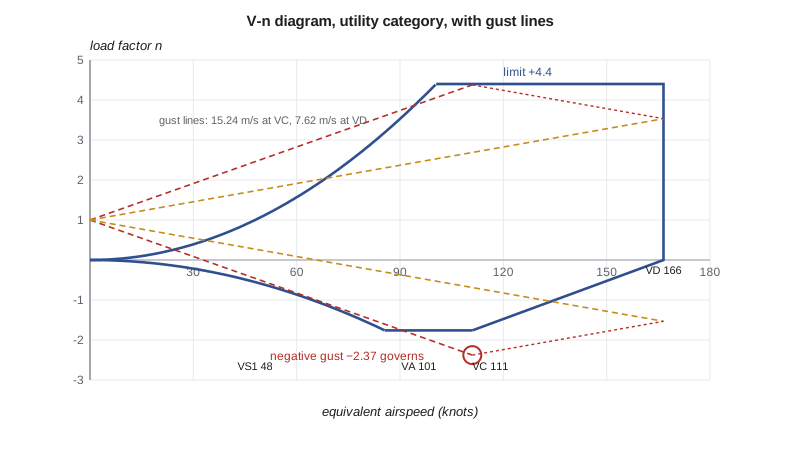
The design cruising speed comes from a formula in the loads standard: at least \(33\sqrt{W/S}\) knots with the wing loading in pounds per square foot, which gives 111 knots, well above the 80-knot cruise the aircraft will actually fly. The dive speed is 1.5 times that in the utility category, 166 knots. The formula exists because pilots do exceed planned speeds, and a light aircraft in a steep spiral dive can reach high speeds quickly. The team keeps the formula's values; lowering them would need a special case the regulator is unlikely to accept for a trainer that students will fly solo.
The result Fatima did not expect is the negative gust. With a mass ratio of 15.2, the gust factor is 0.652 and the gust at cruising speed gives load factors of +4.37 and −2.37. The positive gust is just below the maneuvering limit of 4.4, but the negative gust is well beyond the −1.76 maneuvering limit. The negative ultimate design load factor is therefore −3.56, not −2.64, and the wing's upper surface, which carries the tension in a down load, must be designed for it. Light electric aircraft, with low wing loadings chosen for low stall speeds, often find their envelope set by gusts rather than maneuvers.
The wing structure
The wing is a carbon and glass fiber composite: a single main spar with carbon unidirectional caps and a glass-fiber shear web, a rear spar carrying the flap and aileron hinges, foam-cored sandwich skins and a few ribs at the root, the flap and aileron hinges and the tip. Composite construction suits a laminar aerofoil, whose low drag depends on a smooth, accurately shaped surface that sheet-metal construction struggles to hold. Hélène, who will advise on manufacturing, wants the wing laid up in two half-molds per side, top and bottom, bonded together over the spars, which is how most composite light aircraft are made.
The critical sizing case for the spar caps is the positive ultimate load at 6.6 g. The batteries are in the fuselage, so the wing gets no bending relief from them; only the wing's own mass, about 72 kg, offsets the lift. Fatima estimates the root bending moment from an elliptic lift distribution and sizes the caps for carbon and, for comparison, for aluminum.
# Wing spar cap sizing at the root of the Plover E2 for the positive ultimate load
import math
g, m, m_wing, b = 9.81, 770.0, 72.0, 12.4
n_ult = 6.60
semi = b / 2
y_bar = 4 * semi / (3 * math.pi)                 # centroid of an elliptic half-span load
lift_half = n_ult * (m - m_wing) * g / 2         # wing mass relieves its own bending
M_root = lift_half * y_bar
c_root, tc = 1.40, 0.15
h = 0.85 * tc * c_root                           # distance between cap centroids
F = M_root / h
print(f'semi-span {semi:.2f} m, load centroid {y_bar:.2f} m from the root')
print(f'ultimate half-wing lift {lift_half/1000:.1f} kN, root bending moment {M_root/1000:.1f} kN m')
print(f'cap separation {h*1000:.0f} mm, cap force {F/1000:.0f} kN')
mats = {'carbon/epoxy unidirectional': (480e6, 1550), 'aluminum 2024-T3 extrusion': (290e6, 2780)}
for name, (allow, rho) in mats.items():
    A = F / allow
    mass = A * rho * semi * 2 * 0.55              # caps taper: about 55 % of root area on average
    print(f'{name:30s}: allowable {allow/1e6:.0f} MPa, cap area {A*1e6:5.0f} mm2, both caps both wings {2*mass:5.1f} kg')
# deflection check at limit load, beam with uniform EI equal to 70 % of root value (rough)
E = 120e9; A_c = F / 480e6; I = 2 * A_c * (h / 2) ** 2 * 0.7
w_lim = (n_ult / 1.5) * (m - m_wing) * g / 2 / semi  # uniform equivalent load per meter
delta = w_lim * semi**4 / (8 * E * I)
print(f'tip deflection at limit load (carbon, uniform load estimate): {delta*1000:.0f} mm = {delta/semi*100:.1f} % of semi-span')semi-span 6.20 m, load centroid 2.63 m from the root ultimate half-wing lift 22.6 kN, root bending moment 59.5 kN m cap separation 178 mm, cap force 333 kN carbon/epoxy unidirectional : allowable 480 MPa, cap area 694 mm2, both caps both wings 14.7 kg aluminum 2024-T3 extrusion : allowable 290 MPa, cap area 1149 mm2, both caps both wings 43.6 kg tip deflection at limit load (carbon, uniform load estimate): 483 mm = 7.8 % of semi-span
The root bending moment is 59.5 kN·m and the cap force 333 kN for a cap separation of 178 mm. Carbon caps need 694 mm² each and weigh about 15 kg for both caps of both wings; aluminum caps would weigh about 44 kg. The difference, nearly 30 kg, is worth roughly 1.5 kWh of mission energy in the sizing loop, before the snowball effect on the rest of the aircraft, and confirms the composite choice. The allowable stress of 480 MPa for carbon is far below the material's strength, because it includes knockdowns for compression, for hot and wet conditions, and for the damage the structure must tolerate without being detected, which the next section explains.
The tip deflection at limit load is about 480 mm, nearly 8 percent of the semi-span. That is large but normal for a high aspect ratio composite wing; gliders deflect far more. It matters for the aileron controls, which must not bind when the wing bends, and for the flutter analysis, which the team identifies as necessary but beyond the capstone. The team records flutter as an open item for the certification plan, with the mass balance of the ailerons reserved in the mass statement.
Damage tolerance in composites
A composite structure can be damaged without visible signs, for example by a tool dropped on the wing or a student leaning on the flap, and the damage reduces its compressive strength. Composite aircraft structure is therefore designed so that barely visible impact damage, the largest damage that a routine walk-around inspection might miss, does not reduce the strength below ultimate load, and so that larger, obvious damage still leaves the aircraft able to carry limit load until it is found and repaired. These requirements, and the effects of temperature and moisture on the resin, are why the design allowable is a fraction of the coupon strength. Marcus reminds the team that a trainer is roughly handled on the ground, and that their walk-around inspection checklist is part of the structural design.
The battery bays
The battery is the most energetic and least familiar item in the aircraft, and the battery bays are where the team spends most of its detailed design time. Each pack is about 150 kg of cells, cooling plates, busbars, battery management electronics and an enclosure. The bays must do four things: hold the pack in place in a crash, contain a thermal runaway in any cell, keep high voltage away from people, and keep the cells within their temperature range.
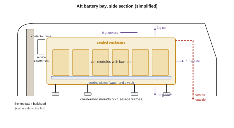
For crash loads the team uses the emergency landing inertia factors the older rules gave for items of mass that could injure the occupants if they broke loose: 9 g forward, 3 g upward, 6 g downward and 1.5 g sideward, applied as ultimate loads. A 150 kg pack under 9 g forward exerts 13.2 kN, the weight of more than a metric ton, on its mounts. For the aft pack, directly behind the occupants' heads, the team adds margin above these factors and designs the mounts so that they fail by bending and absorbing energy rather than by snapping. Rachel expects the regulator to set specific conditions for the battery installation, and the team records the factors as its own design values, to be confirmed in the certification plan.
Thermal runaway is the hazard that most distinguishes the electric aircraft. If a cell shorts internally, overheats or is overcharged, it can enter a self-sustaining reaction that releases heat and flammable gas, and the heat can spread to neighboring cells. The design follows the principle that one cell going into runaway must not lead to a fire that threatens the aircraft. The cells sit in modules with barriers that slow propagation; the enclosure is sealed and fire-resistant; and gas is vented through a duct to an outlet on the underside of the fuselage, away from the cabin air inlet and the occupants. Lucas plans to verify the barriers with a propagation test on a module, deliberately driving one cell into runaway, which is the kind of test the certification authorities expect.
High voltage is the second new hazard. The bus runs at about 400 V, enough to kill. The cables are orange, routed in conduits away from the cabin and separated from low-voltage wiring. An insulation monitor detects a fault to the airframe. Each pack has a main contactor that opens automatically on a crash sensor or a battery fault, a fuse that clears a short circuit, and a manual service disconnect that a technician removes before any maintenance. The aircraft also has an ordinary 28 V system for avionics and lights, supplied from the high-voltage bus by a converter, with a small backup battery so that the radio, transponder and essential instruments keep working if the main packs disconnect.
Cooling uses a water and glycol loop through plates under the cell modules, a small pump and a radiator in the cowling, shared with the motor and inverter but with separate valves so that one pack's loop can be isolated if it leaks. The loop also heats the battery on the ground, with an electric heater powered by the charger, which is how R10's pre-conditioning works.
Interfaces and the mass statement
Detailed design brings parts designed by different people together, and the places they meet are where errors hide. The team writes an interface control document for each major interface: the battery bay and the fuselage frames, the motor mount and the firewall, the wing and fuselage attachment, the cooling loop and every component on it. Each document defines the geometry, loads, electrical connections, fluid connections and responsibilities on both sides, and both owners sign it. When Fatima moved the wing aft by 10 cm to reduce the static margin found in lesson 6, three interface documents changed, and the change rule in the charter made sure all three owners knew.
Mass is tracked in a mass statement, item by item, against the budget from the sizing loop. At the end of detailed design the airframe and systems are 12 kg over budget: the battery enclosures and crash mounts are heavier than the fraction assumed in sizing, the cooling loop added a pump and heater, and the 28 V backup battery was not in the original list. The team reruns the sizing loop with the new empty mass: the aircraft grows to about 790 kg and the battery by about 8 kg, the snowball effect described in lesson 5. Instead of accepting the growth, the team looks for mass to take out: the aluminum seat frames become composite, the backup battery is downsized to the 30 minutes the avionics need, and the wing's foam core is thinned where the analysis shows margin. The design returns to 772 kg, 2 kg over the 770 kg target, which the team reports as it is.
Worked problem
Crash load on a battery mount
The front pack, 150 kg, is held by four mounts. What load does each mount carry under the 9 g forward emergency landing factor, if the load is shared equally, and what does the mount need to carry if it is designed with an additional fitting factor of 1.15?
Show solution
- Total forward load: \(150 \times 9 \times 9.81 = 13{,}240\) N.
- Per mount, shared equally: \(13{,}240/4 = 3{,}310\) N.
- With the fitting factor: \(3{,}310 \times 1.15 = 3{,}810\) N.
- Real mounts do not share equally; the design must consider the worst distribution, often by assuming that two mounts carry most of the load.
Answer: About 3.3 kN per mount, 3.8 kN with the fitting factor; the design should also check uneven load sharing.
Common mistakes
MistakeAssuming the maneuvering limit sets the whole envelope.
InsteadCheck the gust lines; light wing loadings often make gusts govern, especially negative ones.
MistakeUsing coupon strength as the composite design allowable.
InsteadApply knockdowns for environment, compression and barely visible damage.
MistakeTreating the battery as just another mass item.
InsteadDesign for crash retention, thermal runaway containment, high-voltage safety and cooling.
MistakeHiding mass growth.
InsteadTrack mass item by item, rerun the sizing loop when it grows, and report the remaining overrun.
Summary and key terms
- Detailed design carries the wing structure and battery bays to part level.
- The Plover E2 uses the utility category for spin training: limit load factors of +4.4 and −1.76, design speeds of 111 and 166 knots.
- Its light wing loading makes the negative gust at cruise speed, −2.37, exceed the maneuvering limit, so the negative ultimate load is −3.56.
- The composite wing's root bending moment at 6.6 g is 59.5 kN·m; carbon spar caps save about 30 kg over aluminum; tip deflection at limit load is about 8 percent of the semi-span.
- Composite allowables include knockdowns for damage tolerance.
- Battery bays provide crash retention at 9 g forward, thermal runaway containment with an overboard vent, high-voltage isolation and liquid cooling with ground pre-conditioning.
- Interface control documents and a mass statement keep the parts consistent; mass growth of 12 kg was recovered to 2 kg.
- Limit load
- Largest load expected in service.
- Ultimate load
- Limit load times the factor of safety, carried without failure.
- Gust alleviation factor
- Factor reducing the sharp-edged gust load for the aircraft's response.
- Barely visible impact damage
- Composite damage that a routine inspection might miss.
- Thermal runaway
- Self-sustaining overheating reaction in a lithium-ion cell.
- Interface control document
- Signed definition of how two parts of the design connect.
Practice problems
Work each problem on paper first, then reveal the answer to check.
Why does the Plover E2 use the utility category?
Show answer
The school needs intentional spins for training, which require utility category load factors.
Which load case sets the negative design load?
Show answer
The negative gust at the design cruising speed, −2.37 limit, −3.56 ultimate.
How much mass do carbon spar caps save over aluminum?
Show answer
About 30 kg for both caps of both wings.
What are the four functions of the battery bays?
Show answer
Crash retention, thermal runaway containment, high-voltage protection and temperature control.
How did the team handle the 12 kg mass growth?
Show answer
Reran the sizing loop to see the snowball, then took out mass to return to 772 kg, and reported the 2 kg overrun.
Lesson quiz · 5 questions
Score 60% or more to complete this lesson.
Create a free account to save your progress, take quizzes and earn a certificate.