
AERO-300 · Lesson 5 of 12 · 24 min
Airfoil geometry and data
With the theory of the last four lessons in hand, Arjun turns to the practical question that started the Block 2 wing: which airfoil sections should it use? The original Tern wing used a single section from root to tip. Tomasz wants a thicker section at the root, where the wing carries the most bending and needs room for the spar and the fuel or battery bays, and a thinner one at the tip, chosen so that the tip stalls after the root. This lesson covers how airfoils are described, the families that engineers still use, and where reliable section data come from.
Describing an airfoil
An airfoil is the cross-section of a wing cut parallel to the free stream. The chord line joins the leading edge, the most forward point, to the trailing edge. Its length is the chord \(c\), and every other dimension is quoted as a fraction of it. The mean camber line lies halfway between the upper and lower surfaces, measured perpendicular to itself. Its greatest distance from the chord line is the maximum camber, and its position along the chord matters almost as much as its size. The thickness distribution, measured perpendicular to the camber line, has a maximum thickness ratio \(t/c\) and a position of maximum thickness. The leading-edge radius describes how blunt the nose is, and the trailing-edge angle how sharply the surfaces meet.
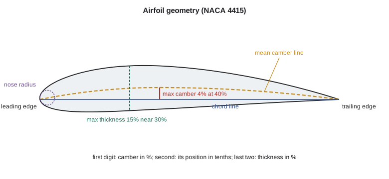
Each geometric feature has an aerodynamic job. Camber shifts the lift curve, so a cambered section produces lift at zero angle of attack and reaches a higher maximum lift, at the cost of a nose-down pitching moment that the tail must balance. Thickness adds structural depth and volume and, up to a point, raises the maximum lift by giving the flow a gentler path around a rounder nose. Too much thickness steepens the pressure recovery on the rear and adds drag. The position of maximum thickness and the shape of the forward surfaces control how far laminar flow can extend, and the leading-edge radius controls how the section stalls.
The NACA four-digit and five-digit families
In the late 1920s and 1930s, engineers at the National Advisory Committee for Aeronautics in the United States, the forerunner of NASA, set out to replace the hundreds of unrelated airfoil shapes then in use with systematic families defined by equations. The first, the four-digit series, combines a standard thickness distribution with a camber line made of two parabolic arcs. The digits are a code: the first gives the maximum camber in percent of chord, the second its position in tenths of chord, and the last two the maximum thickness in percent. The NACA 0012 is symmetrical and 12 percent thick; the NACA 4415 has 4 percent camber at 40 percent chord and is 15 percent thick.
The thickness equation above, with \(x\) as a fraction of chord, has its maximum thickness at 30 percent chord for every section in the family. The last coefficient as originally defined leaves a very small trailing-edge thickness; changing it to minus 0.1036 closes the trailing edge exactly, which is convenient for computer methods. The five-digit series, introduced a little later, moved the maximum camber further forward, around 15 percent chord, which gave higher maximum lift and smaller pitching moments. The NACA 23012 and 23015 became some of the most widely used sections in history and still appear on many general aviation aircraft.
# NACA four-digit airfoil generator: camber line, thickness and surface points
import math
def naca4(code, n=40, closed=True):
    m, p, t = int(code[0]) / 100, int(code[1]) / 10, int(code[2:]) / 100
    a4 = -0.1036 if closed else -0.1015          # closed or slightly open trailing edge
    pts = []
    for i in range(n + 1):
        x = 0.5 * (1 - math.cos(math.pi * i / n))  # cosine spacing clusters points at both ends
        yt = 5 * t * (0.2969 * math.sqrt(x) - 0.1260 * x - 0.3516 * x**2 + 0.2843 * x**3 + a4 * x**4)
        if m == 0: yc, dy = 0.0, 0.0
        elif x < p: yc, dy = m / p**2 * (2 * p * x - x * x), 2 * m / p**2 * (p - x)
        else: yc, dy = m / (1 - p)**2 * ((1 - 2 * p) + 2 * p * x - x * x), 2 * m / (1 - p)**2 * (p - x)
        th = math.atan(dy)
        pts.append((x, yc, yt, x - yt * math.sin(th), yc + yt * math.cos(th), x + yt * math.sin(th), yc - yt * math.cos(th)))
    return pts
for code in ('0012', '4412', '4415'):
    P = naca4(code)
    tmax = max(2 * q[2] for q in P); xt = [q[0] for q in P if abs(2 * q[2] - tmax) < 1e-9][0]
    cmax = max(q[1] for q in P)
    area = sum((P[i + 1][0] - P[i][0]) * (P[i + 1][2] + P[i][2]) for i in range(len(P) - 1))
    le_r = 1.1019 * (int(code[2:]) / 100) ** 2
    print(f"NACA {code}: t/c = {tmax:.3f} at x/c = {xt:.2f}, camber {cmax:.3f}, "
          f"section area {area:.4f} c^2, nose radius {le_r:.4f} c")
print(" x/c    upper y/c  lower y/c   (NACA 4415)")
for q in naca4('4415', 10):
print(f"{q[0]:6.3f} {q[4]:9.4f} {q[6]:9.4f}")NACA 0012: t/c = 0.120 at x/c = 0.31, camber 0.000, section area 0.0816 c^2, nose radius 0.0159 c NACA 4412: t/c = 0.120 at x/c = 0.31, camber 0.040, section area 0.0816 c^2, nose radius 0.0159 c NACA 4415: t/c = 0.150 at x/c = 0.31, camber 0.040, section area 0.1020 c^2, nose radius 0.0248 c x/c upper y/c lower y/c (NACA 4415) 0.000 0.0000 0.0000 0.024 0.0366 -0.0271 0.095 0.0737 -0.0401 0.206 0.1024 -0.0412 0.345 0.1137 -0.0352 0.500 0.1049 -0.0272 0.655 0.0836 -0.0180 0.794 0.0556 -0.0101 0.905 0.0280 -0.0045 0.976 0.0075 -0.0011 1.000 -0.0000 0.0000
The program generates the surface by placing the thickness perpendicular to the camber line, which is why the upper and lower coordinates are not simply the camber plus and minus the thickness. Cosine spacing clusters points near the leading and trailing edges, where the surface curves fastest; any program that integrates pressure around an airfoil, such as the panel method in Lesson 7, needs that clustering. The section area grows in proportion to thickness, 0.0816 \(c^2\) for a 12 percent section and 0.1020 \(c^2\) for 15 percent, which tells the structures group how much room the wing box has. The leading-edge radius grows with the square of thickness, so the 15 percent section has a nose more than half again as blunt as the 12 percent section.
Laminar-flow sections and modern design
During the Second World War, NACA developed the six-series sections, designed so that the pressure kept falling over the forward part of the surface. A falling pressure, a favorable gradient, helps keep the boundary layer laminar, and a laminar boundary layer has much lower skin friction than a turbulent one, as Lesson 10 shows. A six-series designation such as 65-415 gives the series, the position of minimum pressure in tenths of chord, the design lift coefficient in tenths and the thickness in percent. The sections showed a drag bucket: a range of lift coefficients over which the drag is unusually low. In service, insects, rain and manufacturing roughness often tripped the boundary layer early and erased much of the benefit, but the sections remained popular because of their good high-speed behavior.
Since the 1970s, most new airfoils have been designed for a specific aircraft rather than taken from a catalog. Inverse design methods start from a desired pressure distribution and compute the shape that produces it, and coupled inviscid-viscous programs such as XFOIL, written at the Massachusetts Institute of Technology in the 1980s, predict lift, drag and transition quickly enough to explore thousands of candidates. Natural-laminar-flow sections designed this way, with smooth composite skins, now achieve laminar flow over a large part of the chord on business jets and light aircraft. Supercritical sections, flattened on top to delay shock waves, dominate transport aircraft and are a topic for AERO-310.
Where section data come from
The classic reference is the book by Ira Abbott and Albert von Doenhoff, published in 1949 and still in print, which collects NACA wind-tunnel data for the four-digit, five-digit and six-series sections. For each section it gives the lift curve, the drag polar and the pitching moment at several Reynolds numbers between about 3 and 9 million, measured in a two-dimensional tunnel where the model spans the test section from wall to wall so that no tip vortices form. For low Reynolds numbers, the University of Illinois at Urbana-Champaign maintains an airfoil coordinates database with well over a thousand sections and has published low-speed test data for many of them, widely used for drones and small aircraft. Many aircraft companies, Prairiewind Aerospace included, also maintain their own databases of tunnel tests and validated computations.
When using section data, three cautions apply. First, the Reynolds number must match the application: maximum lift and drag both depend on it, and data at 9 million can be optimistic for a small wing tip at 2.6 million. Second, the surface condition matters: Abbott and von Doenhoff also give data with standard leading-edge roughness, and the difference in maximum lift and drag is large. Third, section data describe an infinite wing. The finite wing's lift slope, maximum lift and drag differ, as Lessons 8, 9 and 11 explain.
| Quantity | NACA 0012 | NACA 4412 | NACA 4415 |
|---|---|---|---|
| Maximum camber | 0 | 4% at 40% | 4% at 40% |
| Thickness | 12% | 12% | 15% |
| Zero-lift angle (thin airfoil theory) | 0° | −4.15° | −4.15° |
| Moment coefficient about c/4 (thin airfoil theory) | 0 | −0.106 | −0.106 |
| Typical clmax, smooth, Re about 6 million | about 1.5–1.6 | about 1.6–1.7 | about 1.6–1.7 |
| Typical minimum cd, smooth, Re about 6 million | about 0.006 | about 0.006 | about 0.0065 |
Choosing the Block 2 sections
Tomasz's group shortlisted sections against five criteria: maximum lift at the landing Reynolds number, drag at the cruise lift coefficient of about 0.45, pitching moment, stall character and thickness for structure. They chose the NACA 4415 at the root and the NACA 4412 at the tip, blended linearly between. Both have the same camber line, so the wing has uniform zero-lift angle and pitching moment along the span, which keeps the lifting-line calculation of Lesson 9 simple, and the thinner tip section has a slightly more forgiving stall at the tip Reynolds number. Arjun asked why the team had not chosen a modern custom section. Tomasz's answer was practical: the Block 2 wing must be certified on a tight schedule, the four-digit sections have a vast body of test data and service experience, and their trailing-edge stall, explained in Lesson 11, is gentle. A custom natural-laminar-flow section might save two or three drag counts in cruise, but only on a perfectly clean wing, and the Tern operates from gravel strips where the leading edges are sandblasted every week.
Worked problem
Reading the four-digit code
Describe the NACA 2415 section and find its maximum thickness and camber in millimeters on the Block 2 root chord of 2.27 m.
Show solution
- First digit 2: maximum camber 2 percent of chord. Second digit 4: located at 40 percent chord.
- Last two digits 15: maximum thickness 15 percent of chord, at 30 percent chord for the four-digit thickness form.
- On a 2.27 m chord: thickness \(0.15\times 2270 = 340\ \text{mm}\), camber \(0.02\times 2270 = 45\ \text{mm}\) at 908 mm behind the leading edge.
Answer: The NACA 2415 has the same thickness as the 4415 but half the camber. It would give a smaller nose-down moment and a slightly lower maximum lift.
Worked problem
Wing box depth from the section geometry
The main spar of the Block 2 wing sits at 30 percent chord at the root. Using the NACA 4415 coordinates at 34.5 percent chord from the program, estimate the depth available for the spar on the 2.27 m root chord.
Show solution
- At \(x/c = 0.345\) the upper surface is at 0.1137 and the lower at −0.0352.
- Depth: \((0.1137 + 0.0352)\times 2.27 = 0.338\ \text{m}\).
Answer: About 338 mm, less the skin thicknesses, is available for the spar web. Marcus Webb's structures group uses exactly this kind of number to size the spar caps, which is why the root section is the thickest one the aerodynamic requirements allow.
Common mistakes
MistakeReading the second digit of a NACA four-digit code as a percentage.
InsteadIt is the camber position in tenths of chord: 4 means 40 percent.
MistakeApplying section data measured at 9 million to a small wing at 1 million.
InsteadMaximum lift and drag change with Reynolds number. Use data at the right Reynolds number or correct for it.
MistakeTreating section lift and drag as the wing's lift and drag.
InsteadSection data are for infinite span. The finite wing has a lower lift slope, induced drag and different maximum lift.
MistakeExpecting laminar-flow sections to keep their low drag in service.
InsteadInsects, rain, ice and roughness trip the boundary layer. The benefit is real only with smooth, clean surfaces.
Summary and key terms
- An airfoil is described by its chord, camber line, thickness distribution, leading-edge radius and trailing-edge angle.
- Camber shifts the lift curve and adds a nose-down moment; thickness adds structural depth and affects maximum lift and drag.
- The NACA four-digit, five-digit and six-series families define shapes by equations and codes, and modern sections are usually designed for each aircraft with inverse and viscous-inviscid methods.
- Section data must match the Reynolds number and surface condition of the application.
- The Block 2 wing uses the NACA 4415 at the root and 4412 at the tip.
- Chord line
- The straight line from the leading edge to the trailing edge.
- Mean camber line
- The line halfway between the upper and lower surfaces.
- Thickness ratio
- Maximum thickness divided by chord.
- Leading-edge radius
- The radius of the circle that fits the nose of the section.
- NACA four-digit series
- A family of sections defined by camber, camber position and thickness digits.
- Six-series section
- A NACA family designed for extended laminar flow over the forward surfaces.
- Drag bucket
- A range of lift coefficients with unusually low drag on a laminar-flow section.
- Two-dimensional test
- A wind tunnel test in which the model spans the test section so no tip vortices form.
Practice problems
Work each problem on paper first, then reveal the answer to check.
Describe the NACA 6409 section.
Show answer
6 percent camber at 40 percent chord, 9 percent thick.
What is the maximum thickness, in millimeters, of a NACA 0012 with a 1.0 m chord, and where is it?
Show answer
120 mm at 300 mm behind the leading edge.
Why does the Block 2 wing use the same camber line at the root and tip?
Show answer
So the zero-lift angle and pitching moment are the same along the span, which simplifies the analysis and avoids aerodynamic twist.
In the program, generate the NACA 2412. What are its maximum camber and section area?
Show answer
Camber 0.020 at x/c = 0.40; area 0.0816 c², the same as any 12 percent four-digit section.
Why might a 15 percent section have a higher maximum lift than a 9 percent section with the same camber?
Show answer
Its larger leading-edge radius lowers the suction peak at high angle of attack, delaying leading-edge separation.
What two corrections should be considered before using catalog data at the wing tip?
Show answer
Reynolds number and surface roughness, then three-dimensional effects.
Lesson quiz · 5 questions
Score 60% or more to complete this lesson.
Create a free account to save your progress, take quizzes and earn a certificate.