
WLD-230 · Lesson 10 of 12 · 16 min
Bend test coupons: cutting, preparing and bending
A groove weld test is decided by bending. The test plate is cut into strips across the weld, the strips are ground flat, and each one is forced around a mandrel until it is bent into a U. The outside of the bend stretches by about a fifth of its length, and anything in the weld that is not sound metal, such as lack of fusion, slag, porosity or a crack, opens up into a visible tear. A good weld bends like the plate around it. Devon has been bending practice coupons since week three, and in this lesson Lucia shows him how the specimens are laid out, cut and prepared so that the bend tests the weld and not the cutting, and how the results are judged.
Why bend tests work
A weld can look perfect on the surface and hide a line of slag between two passes or a cold lap along a sidewall. Radiography can find many of these defects, but it needs equipment and a licensed technician, and planar defects such as lack of sidewall fusion can be missed if they lie at the wrong angle to the beam. A bend test is simple, cheap and very good at finding exactly the defects a welder is most likely to make. When a specimen is bent, the outside surface is stretched, and any discontinuity on or near that surface concentrates the strain and opens. Sound weld metal and heat-affected zone stretch evenly with the plate.
The amount of stretch is set by the thickness of the specimen and the diameter of the mandrel. For a specimen of thickness t bent around a mandrel of diameter D, the strain on the outside surface is approximately:
With the mandrel about four times the specimen thickness, the outer surface stretches by about 20 percent, which is well within what good structural steel and weld metal can take and far more than a weld with a defect can.
Face, root and side bends
There are three kinds of transverse bend specimen, named for the surface that ends up on the outside of the bend, in tension:
- A face bend puts the face of the weld, the cap side, on the outside. It tests the cap and the upper fill passes.
- A root bend puts the root side on the outside. On a backed plate, the backing is removed first, and the bend tests the fusion of the root into the bevel corners and the backing line.
- A side bend is cut from thicker plate and bent so that a cut cross-section of the weld, showing every pass from root to cap, is on the outside. It tests the whole weld at once.
For a 10 mm (3/8 in) plate test, the CWB practice is to split the coupon and take one root bend and one face bend from it. For thicker test plates, side bends are used, because a full-thickness face or root bend on thick plate would need a very large mandrel and press. Lucia's test plan for Devon follows the CWB practice for each position he tests.
A face or root bend on the test plate is made with the specimen at the full plate thickness. The reinforcement on the face and the backing on the root side are ground or machined flush with the plate, so that the specimen is a flat strip of even thickness with the weld running across its middle.
Laying out the specimens
The specimens are taken from the middle of the test plate, where the welding is representative. The first and last part of each plate, about 25 mm (1 in) at each end, are cut off and discarded, because starts and stops are not what the test is meant to judge. The specimens are cut across the weld, so that each specimen has weld metal in its middle and plate on both sides.
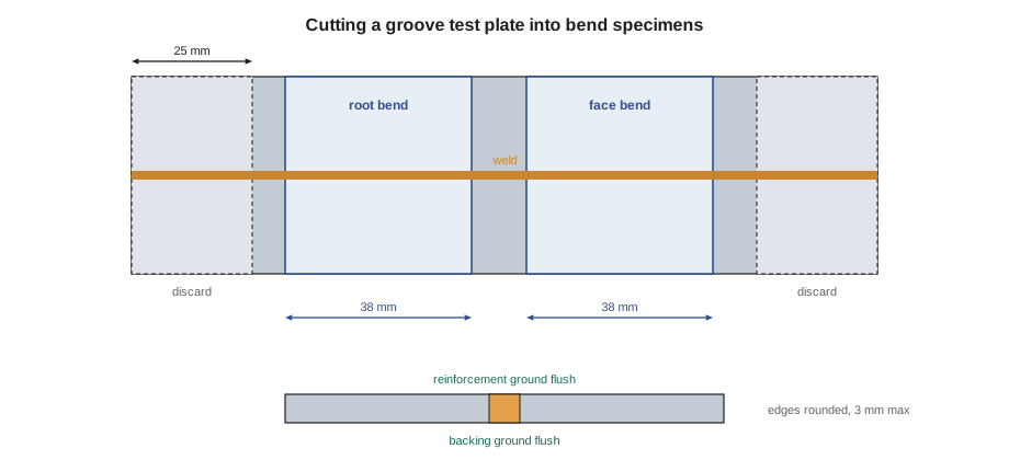
# Bend specimen cut list and bend geometry for a groove test plate
PLATE_LEN, T = 150, 10          # length of the test plate along the weld and its thickness, mm
DISCARD, WIDTH, KERF = 25, 38, 3
SPECIMENS = ["root bend", "face bend"]
used = 2 * DISCARD + len(SPECIMENS) * WIDTH + (len(SPECIMENS) + 1) * KERF
print(f"plate {PLATE_LEN} mm long: needs {used:.0f} mm for {len(SPECIMENS)} specimens, {PLATE_LEN - used:.0f} mm spare")
x = DISCARD + KERF
for name in SPECIMENS:
    print(f"  {name:10} from {x:.0f} to {x + WIDTH:.0f} mm")
    x += WIDTH + KERF
D = 38                          # mandrel (plunger) diameter, about 4 t
strain = T / (D + T)
print(f"mandrel {D} mm for {T} mm specimens: outer surface strain about {100 * strain:.0f}%")
print(f"die opening about D + 2t + clearance = {D + 2 * T + 3:.0f} mm")plate 150 mm long: needs 135 mm for 2 specimens, 15 mm spare root bend from 28 to 66 mm face bend from 69 to 107 mm mandrel 38 mm for 10 mm specimens: outer surface strain about 21% die opening about D + 2t + clearance = 61 mm
The layout shows how little spare plate there is on a short test plate, which is why the test plate length in the procedure must not be cut down. If a specimen is spoiled in cutting, there may not be enough plate left to cut another from the same weld.
Cutting
The specimens are cut with a band saw or an abrasive saw where possible. Thermal cutting, with oxyfuel or plasma, is allowed by the test standards if the heat-affected edge is removed afterwards by machining or grinding, because a thermally cut edge is hard and rough and can crack on its own when bent. At Hartwell, test plates are cut on the band saw with a coolant flow, which leaves clean, square edges.
Preparing the specimens
Preparation is where a good weld can be made to fail, or a bad one to pass, and Lucia is strict about it.
- Remove the backing and reinforcement flush. The backing is ground or machined off the root side and the cap reinforcement off the face side, so that the specimen is flat and of even thickness. Neither may be ground below the plate surface by more than a slight amount, because thinning the specimen at the weld changes the test.
- Grind lengthwise. Final grinding marks run along the length of the specimen, across the weld, not along the weld. Grinding marks parallel to the weld act like small notches in the direction that opens under the bend.
- Round the edges. The long edges of the specimen, on the tension side, are rounded with a small radius, about 3 mm (1/8 in) or less, so that the sharp corner left by cutting does not start a crack.
- Do not quench. Specimens are not cooled in water after grinding, and they are not heated or straightened. The weld must be tested as welded.
A specimen with a corner crack that started at a poorly rounded edge, with no slag or fusion defect behind it, tells nothing about the weld, and the test rules generally allow it to be replaced by another specimen from the same plate, if there is one. That is another reason to prepare carefully the first time.
The bend
Hartwell's bend jig is a hydraulic plunger-type jig: a rounded plunger of the right diameter pushes the specimen down between two rollers or a shaped die until the specimen wraps into a U around the plunger. Other jigs use a wrap-around design, in which the specimen is clamped at one end and a roller wraps it around a fixed mandrel. Both produce the same result if the dimensions are right.
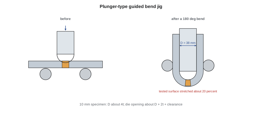
The specimen is placed in the jig with the weld centred under the plunger and the surface to be tested facing away from it, so that it ends up on the outside of the bend. The bend is made slowly and steadily until the specimen has been bent through 180 degrees, or as far as the jig allows, and the legs are parallel. Devon's first bend on the jig is a good practice coupon from week four, so that he can see what a good bend looks like before he bends one of his own doubtful ones.
Judging the bend
After bending, the outside surface of the specimen is examined with a good light and, where needed, a magnifier. Lucia uses acceptance limits based on the welder test standards. The limits are written in terms of the size of the largest discontinuity and the total of the smaller ones:
| Feature on the convex surface | Limit |
|---|---|
| Any single discontinuity | No more than 3 mm (1/8 in) in any direction |
| Sum of the larger discontinuities | Total of those over 1 mm (1/32 in) no more than 10 mm (3/8 in) |
| Corner cracks | Not over 6 mm (1/4 in), unless caused by slag or a fusion defect, in which case the 3 mm (1/8 in) limit applies |
| Cracks in the weld or heat-affected zone | Judged by the same size limits; a crack from a fusion defect is a fusion defect |
# Bend specimen evaluation: measured openings on the convex surface (mm)
SINGLE, SUM_LIMIT, SMALL, CORNER = 3.0, 10.0, 1.0, 6.0
def judge(name, openings, corner=None, corner_from_defect=False):
    worst = max(openings, default=0.0)
    total = sum(o for o in openings if o > SMALL)
    ok = worst <= SINGLE and total <= SUM_LIMIT
    if corner is not None:
        ok = ok and corner <= (SINGLE if corner_from_defect else CORNER)
    note = "" if corner is None else f", corner crack {corner} mm" + (" from slag" if corner_from_defect else "")
    print(f"{name:22} largest {worst:.1f} mm, total {total:.1f} mm{note}: {'ACCEPT' if ok else 'REJECT'}")
for args in [("3G face, plate 14", [0.5, 1.5]), ("3G root, plate 14", []), ("4G root, plate 19", [4.5]), ("4G face, plate 19", [1.2, 2.0, 2.5, 2.8, 1.6], None), ("2G root, plate 9", [0.8], 5.0, False), ("1G root, plate 6", [], 4.0, True)]:
judge(*args)3G face, plate 14 largest 1.5 mm, total 1.5 mm: ACCEPT 3G root, plate 14 largest 0.0 mm, total 0.0 mm: ACCEPT 4G root, plate 19 largest 4.5 mm, total 4.5 mm: REJECT 4G face, plate 19 largest 2.8 mm, total 10.1 mm: REJECT 2G root, plate 9 largest 0.8 mm, total 0.0 mm, corner crack 5.0 mm: ACCEPT 1G root, plate 6 largest 0.0 mm, total 0.0 mm, corner crack 4.0 mm from slag: REJECT
The examples are from Devon's own practice log. Plate 14, a 3G plate from week six, passes both bends. Plate 19, a 4G plate from week eight, fails the root bend with a single opening along the backing line, the overhead fault from the last lesson, and also fails the face bend on the total of several small openings, each one acceptable on its own. The 2G root has a corner crack from a sharp edge, under the corner crack limit with no defect behind it. The 1G root shows a corner crack that opened from a slag line, so the smaller limit applies and it fails.
Reading a failed bend
A failed bend is the best teacher a welder has, because the opening shows exactly where the weld went wrong. Lucia has Devon read each failed specimen before she tells him the cause:
| Where it opened | What it usually means |
|---|---|
| Along one bevel line, on the root side | Cold corner: root did not fuse that bevel |
| Along the line of the backing | Root not fused into the backing |
| Between passes in the middle of the weld | Slag or lack of interpass fusion |
| Along a sidewall, on the face side | Lack of sidewall fusion in the upper fill or cap |
| Small round holes | Porosity, often at a restart |
| At the edge of the specimen only | Poor edge preparation, unless slag shows in the crack |
He also keeps every failed specimen, labelled with the plate number, on a board in the training bay. By the end of the course, the board holds about a dozen. Marta says it is the most useful wall in the shop.
Common mistakes
MistakeTaking specimens from the ends of the plate.
InsteadDiscard about 25 mm (1 in) at each end and take the specimens from the middle.
MistakeGrinding the specimen with marks along the weld.
InsteadFinish with grinding marks running the length of the specimen.
MistakeLeaving sharp corners on the specimen edges.
InsteadRound the tension-side edges with a small radius.
MistakeGrinding the weld below the plate surface.
InsteadRemove backing and reinforcement flush, not deeper.
MistakeBending a thermally cut specimen without removing the cut edge.
InsteadSaw-cut, or machine or grind away the heat-affected edge.
Summary and key terms
- Bending stretches the outer surface about 20 percent and opens any discontinuity there.
- Outer surface strain is about t divided by D plus t.
- Face and root bends are used for thinner test plates, side bends for thicker ones.
- Discard the plate ends, cut specimens across the weld and remove backing and reinforcement flush.
- Grind lengthwise, round the edges, and never quench or straighten specimens.
- Judge the convex surface against the single, total and corner crack limits.
- Guided bend test
- A test in which a specimen is bent around a mandrel of set diameter in a jig.
- Face bend
- A bend specimen with the weld face on the outside of the bend.
- Root bend
- A bend specimen with the weld root on the outside of the bend.
- Side bend
- A bend specimen with a cross-section of the weld on the outside of the bend.
- Mandrel
- The rounded former or plunger around which a bend specimen is bent.
- Convex surface
- The outside, stretched surface of a bent specimen.
Practice problems
Work each problem on paper first, then reveal the answer to check.
What is the outer surface strain on a 10 mm specimen bent around a 38 mm mandrel?
Show answer
10 / (38 + 10) = about 21 percent.
A face bend shows one 2.5 mm opening and nothing else. Accept or reject?
Show answer
Accept; it is under the 3 mm single limit.
Why are grinding marks finished along the length of the specimen?
Show answer
Marks along the weld act as notches that open under the bend.
Lesson quiz · 5 questions
Score 60% or more to complete this lesson.
Create a free account to save your progress, take quizzes and earn a certificate.